| |
||
Overview
The ProblemThe acronym PCV stands for Positive Crankcase Ventilation and is a system to ventilate and re-burn the small amount of gases that sneaks past the piston and into the crankcase. Ideally a piston together with the piston rings should keep absolutely tight against the cylinder wall and should not let anything pass. However during the compression stroke, a small amount of gases will escapes past the piston and end up in the crankcase. These gases must be ventilated out from the crankcase. There are several reasons why you want to ventilate out these
so-called blow-by gases:
In earlier days, the blow-by gases were simply ventilated directly into the atmosphere resulting in higher than necessary contribution of automotive-based air pollution. But later emission regulations prohibit such solutions. Tools, Skills And PartsThe job is pretty straightforward and does not include any special tools. Difficulty Level
The following tools are required for this particular work (tools marked with green checkmark are optional).
The following spare parts are required for this particular work (parts marked with green checkmark are optional). Note that the BMW internal numbers are intended for a non-EML BMW 535i E34 -89. Models equipped with EML (Elektronische MotorLeistungsregelung, i.e. electronic throttle control or drive-by-wire, the PCV layout is different and not included here.
PreparationsFour parts of the PCV system can be assembled in advance making the installation later on a little bit easier. The four different parts are shown below together with a picture of them assembled together. 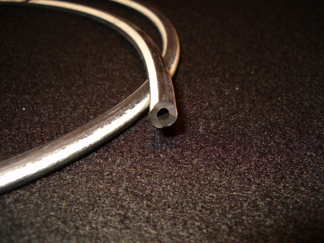
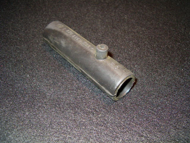
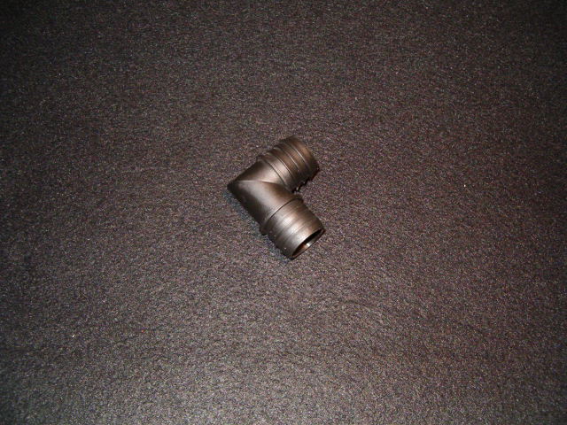
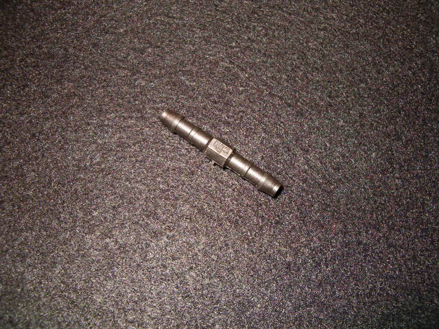
Four parts to be assmebled. From top left to bottom right; vacuum hose, ventilation hose, support and connection piece. 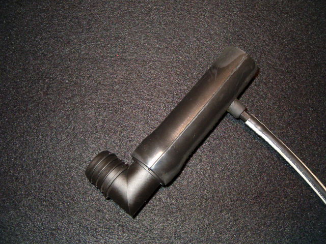 All four parts assembled. |
Removing Old PCVHere follows step-by-step instructions how to remove the old parts and prepare for the new ones in a very easy way (but maybe not the fastest). Note that it is not necessary to remove for example the top of the air filter box or the support for the ICV unit. But by removing these extra things, which is very easily done, it is a lot easier to install the new parts. 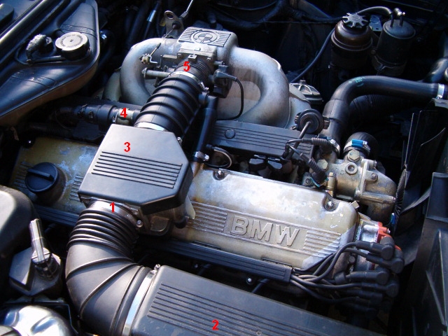 Different parts in the engine compartment numbered out. Air Filter Box : Start by undo all six metal springs holding the top of the air filter box (marked with figure 2 in the picture above). Then loosen the hose clamp (marked with figure 1 in the picture above) at the intake of the air flow meter (marked with figure 3 in the picture above). Use a 6 mm socket (or a flat-blade screwdriver) for the hose clamp. Now lift up the top of the air filter box and disconnect it from the air flow meter. ICV: Now the ICV (Idle Control Valve) is to be disconnected. It is marked with figure 4 in the picture above. The ICV has a support with a mounting point at the valve cover. Remove the nut on the valve cover. Use a 10 mm socket to remove it. Now simply pull the ICV unit straight out from the rubber boot. Air Flow Meter : Next step is to remove the air flow meter. Start by loosen the hose clamp at the output of the air flow meter. Use a 6 mm socket (or a flat-blade screwdriver) for the hose clamp. Now remove the three nuts located directly under the air flow meter. Two of them are hard to get good access to but with a very small 10 mm combination wrench it is possible. As the last thing, disconnect the electrical contact to the air flow meter (located at the same side as the oil cap). Now simply lift the air flow meter straight up to remove it. On the ventilation hose (mounted between the rubber boot and the valve cover) you can see a small vacuum hose connected near the valve cover. The other end is connected under the intake manifold. Feel with your hand under the intake manifold and you will find a metal plug where the vacuum hose is connected to. Just pull it straight out from the intake manifold. If you are not sure or can not find it, it is possible to see it from beneath. Loosen the hose clamp on the ventilation hose at the valve cover connection. Use a 6 mm socket. Loosen the hose clamp connecting the rubber boot to the throttle housing (marked with figure 5 in the picture above). Use a 6 mm socket. Now simply remove the entire rubber boot with ventilation hose and vacuum hose. Mounting New PCVInstalling the new parts is very straight forward. If you pre-assembled the different parts as described earlier, here follows a recommended installation procedure. Press the ICV unit into the rubber boot and then the pre-assembled unit into the other side. Note! The straight end of the rubber boot is to be connected to the throttle housing (and the skew end of the rubber boot to the air flow meter). Mount loosely both ends of the rubber boot to the throttle housing and air flow meter. Mount and fastening first the air flow meter then the support for the ICV unit. Reconnect the electrical contact for the air flow meter. Tighten the hose clamp connecting the ventilation hose to the valve cover. Tighten the hose clamp connecting the rubber boot to the throttle housing and the air flow meter. Don't forget to connect the vacuum hose between the ventilation hose and the bottom of the intake manifold. Finally mount the top of the air filter box, lock with all six metal clips and tighten the hose clamp at the air flow meter intake. |