| |
||
Overview
The ProblemThe problem seems to be quite common on the E30 models. The
fuel and/or temp gauge stops to work from time to time or does
not work at all.
Tools, Skills And PartsThe job is very easy to perform and does not require any kind of special tools. Difficulty Level
The following tools are required for this particular work (tools marked with green checkmark are optional).
The SolutionStart by removing the instrument cluster. At the back there are two main connectors and two wires to the ABS light (if your E30 is equipped with ABS that is). The two main connectors are removed by first pull up the black plastic and then remove the connector. 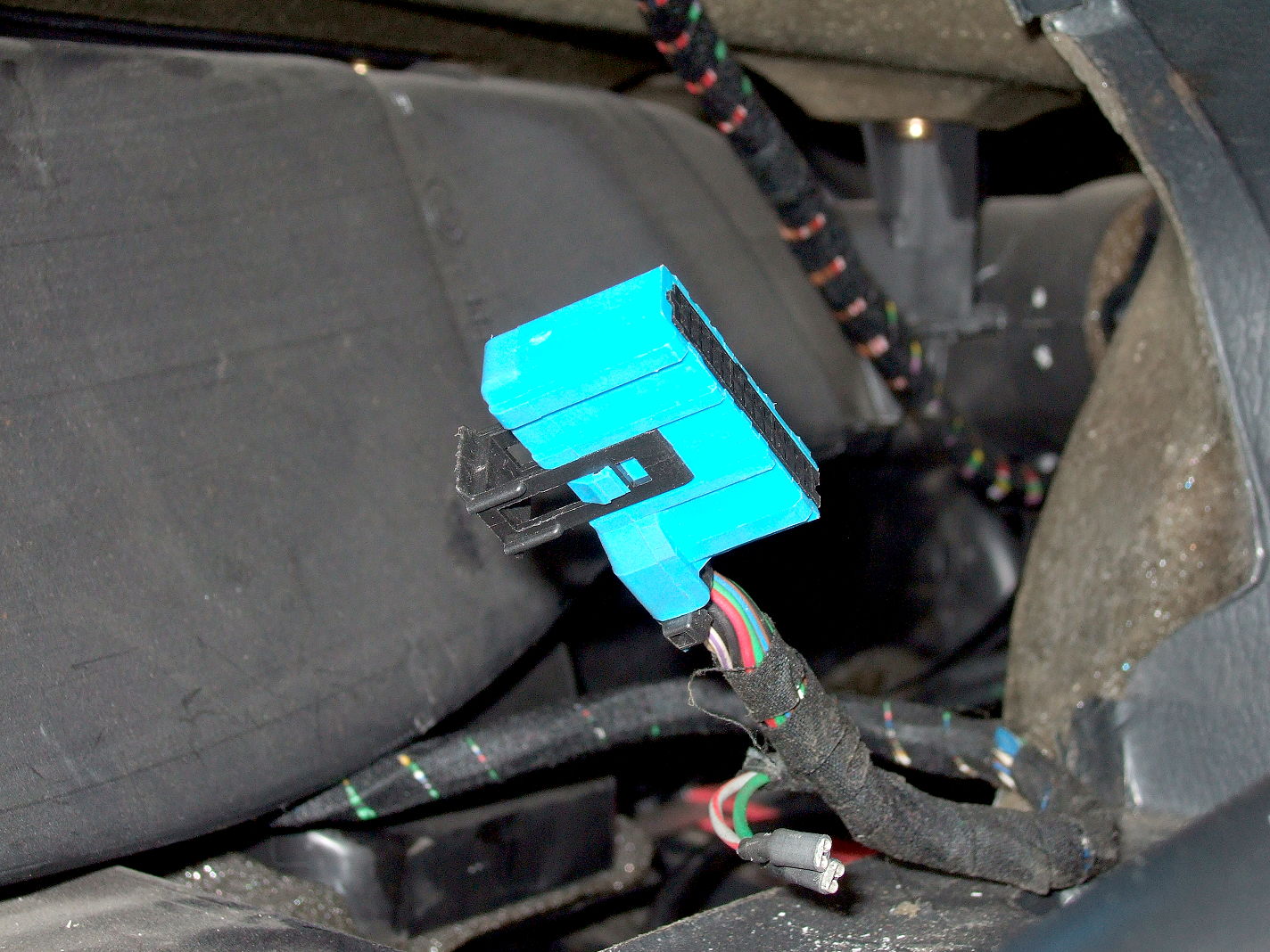 One of the two main connectors located behind the instrument cluster. Note the black plastic clip that is pulled up before removing the connector. Remove the baseplate (including the instruments) from the instrument carrier. You should now have a unit with the gauges accessible at the front and the screws accesible at the rear. 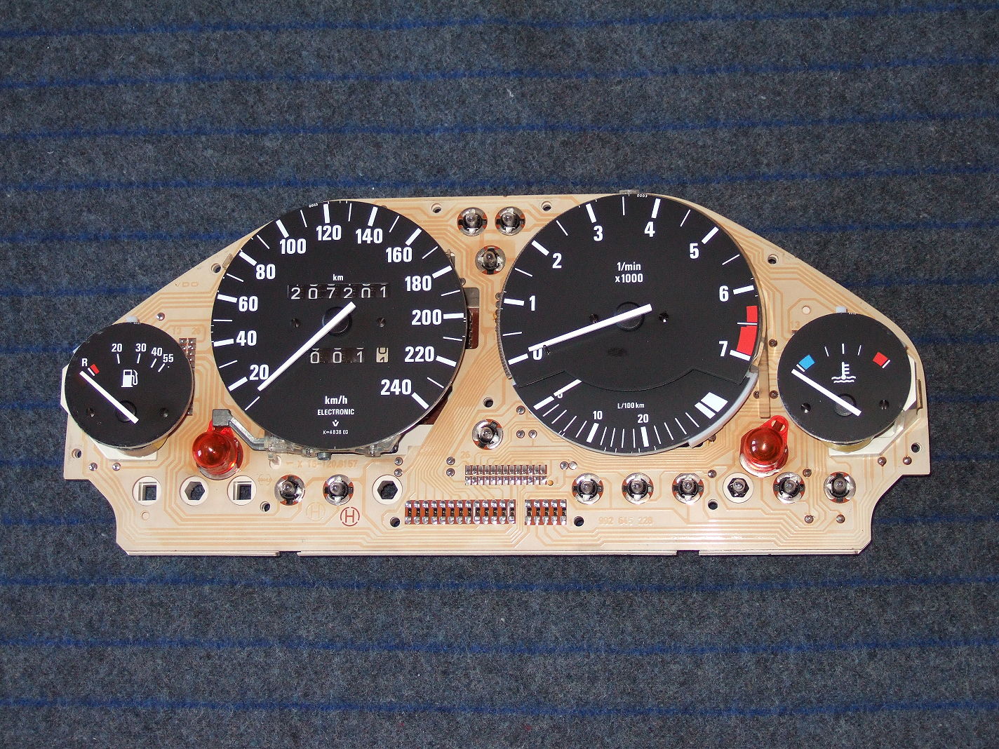 Front of baseplate (including the instruments). 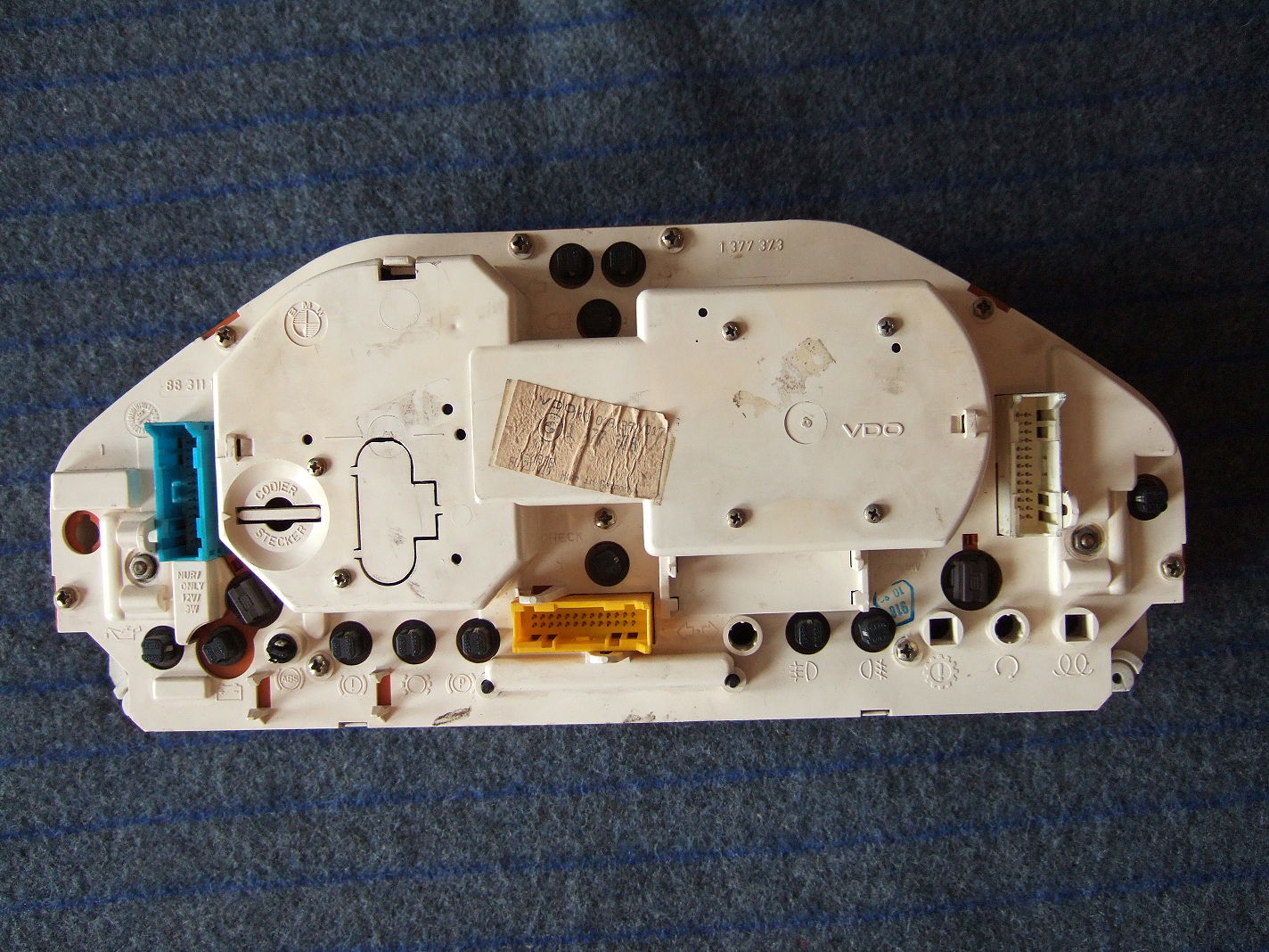 Rear of the baseplate (including the instruments). |
To make the repair you must first separate the front and back. These are held together by nine Phillips screws (having 6 mm hex head). 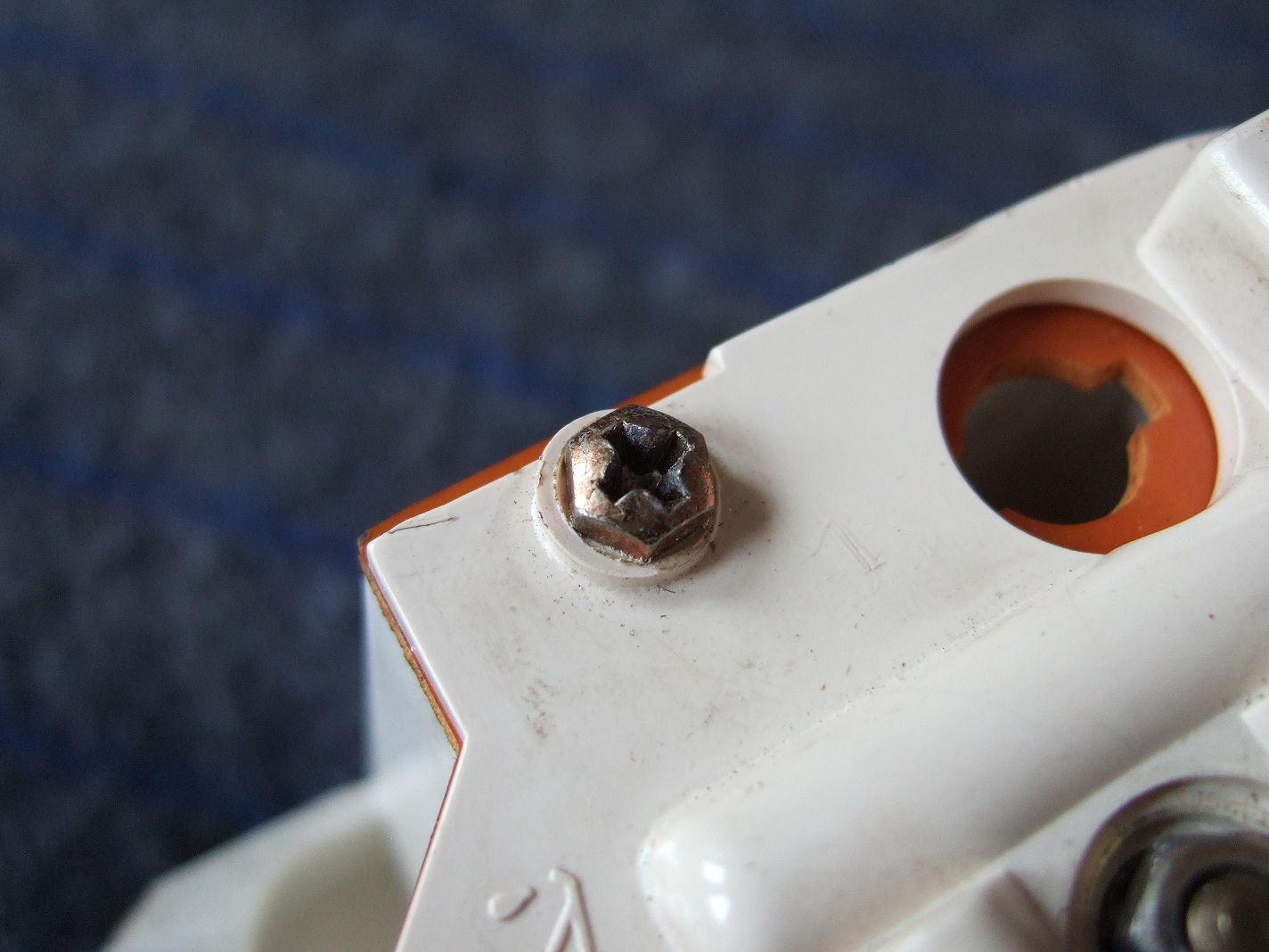 Nine of these Phillips screws are helding the front and back together. Use a 6 mm socket or a a Phillips screwdriver to remove these screws.
Now it's time to remove the gauge which is attached to the PCB using a 7 mm
hex head nut on the rear of the baseplate. This nut is also a part of the grounding
point for the gauge.
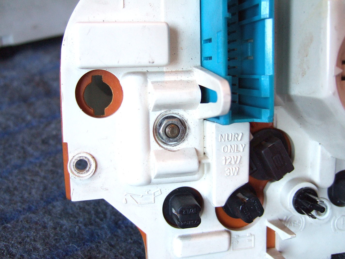 The 7 mm heax head nut holding the gauge together with the PCB. 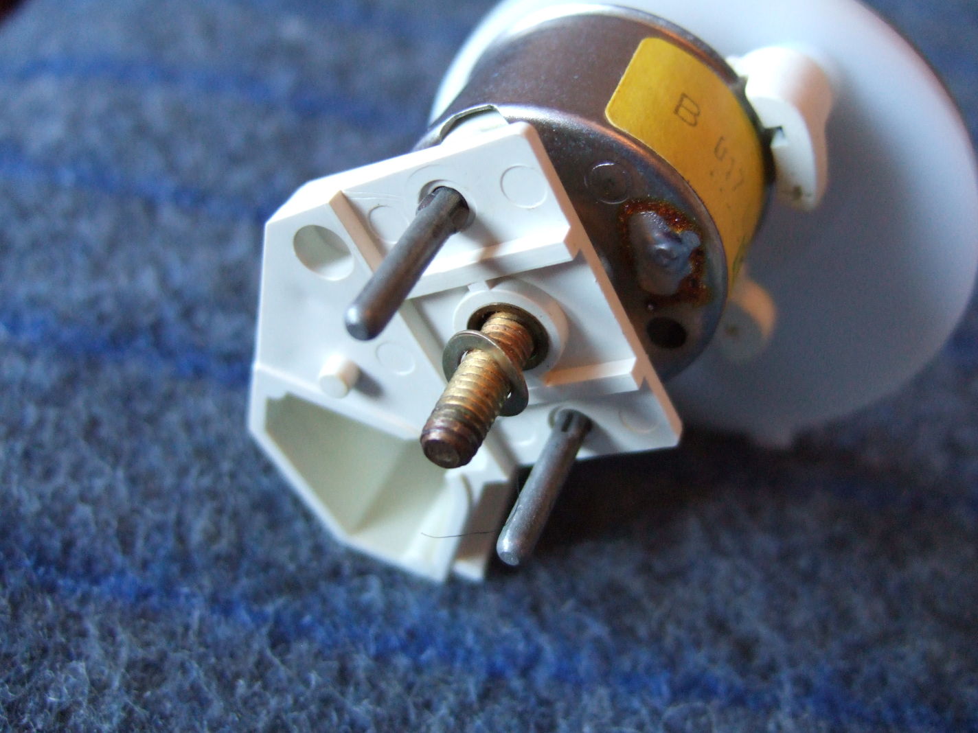 The gauge removed. The two grey pins are used for signals from the sensor and the screw in the middle are used for grounding.
If not a correctly tightened nut was causing the grounding problem then it is most
probably caused by insufficient solder.
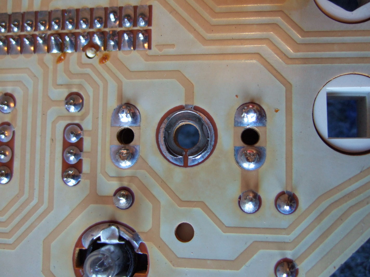 The faulty grounding point on the PCB. The major part of solders is missing causing bad or no grounding contact at all. 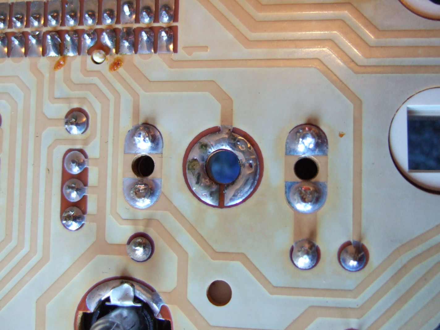 They previously faulty grounding point on the PCB now filled up with new solder providing good grounding contact again. |