Overview
- Introduction
- Tool, Skills And Parts
- Removing Ignition Leads
- Removing Intake Manifold
- Removing Exhaust Manifolds
- Removing Alternator Wiring
- Removing Alternator
- Removing Starter Motor
- Removing Thermostat Housing
- Removing Water Pump
Introduction
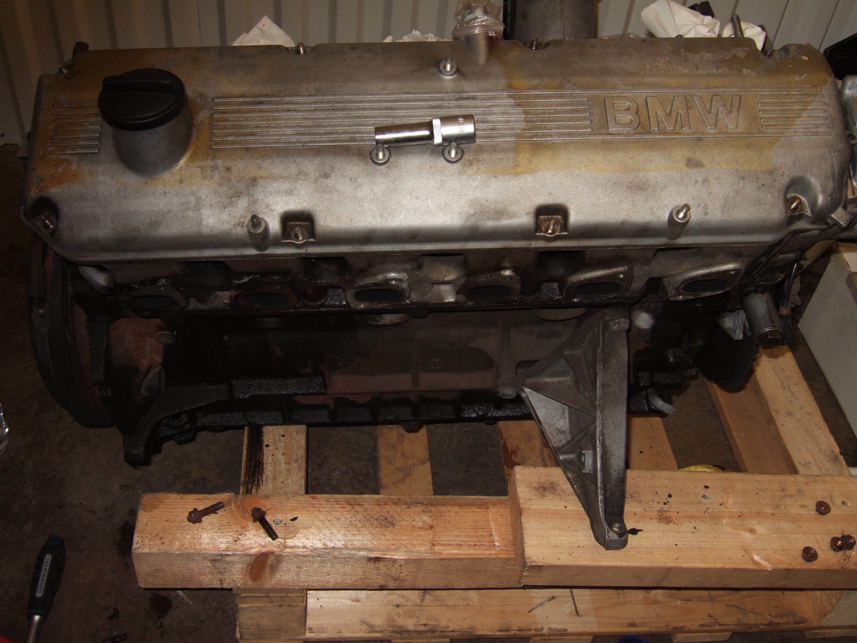
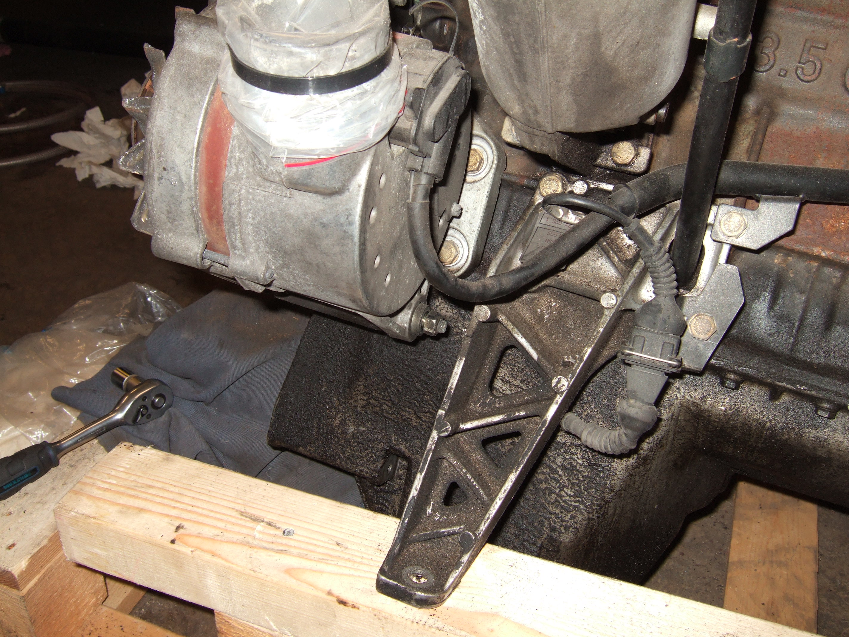
In this part we assume the engine has just been removed from the car so all descriptions are based on that the engineis placed on a suitable stand, like the one in Picture 1. We will in this part remove the following parts from the engine
- ignition leads
- intake manifold
- exhaust manifold
- alternator wiring
- alternator
- starter motor
- thermostat housing
- water pump

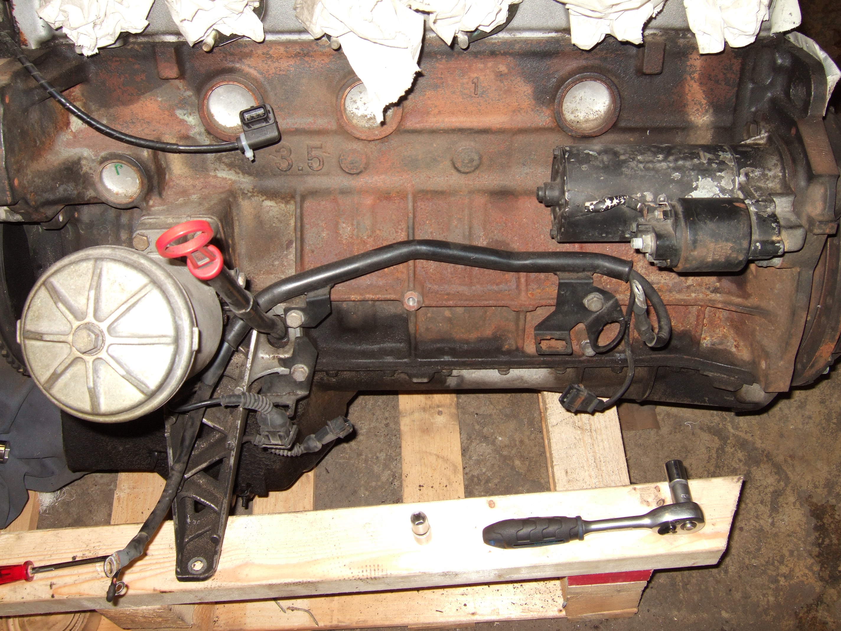
Picture 1 : The starting point - a complete M30B35 engine now resting on it's two mounting brackets and the reinforced part of the oil pan.
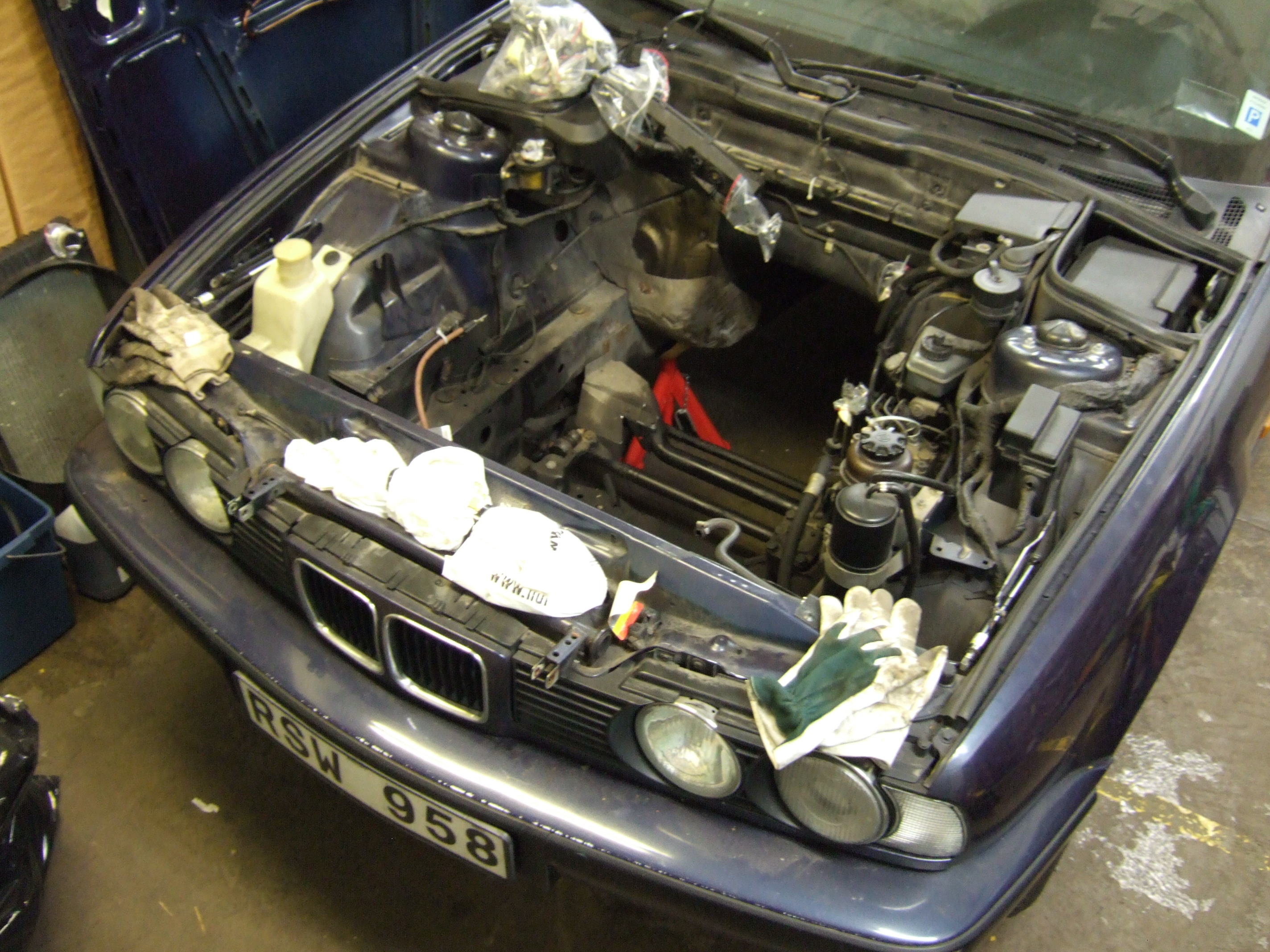
Picture 2 : With the engine removed the engine bay looks quite empty.
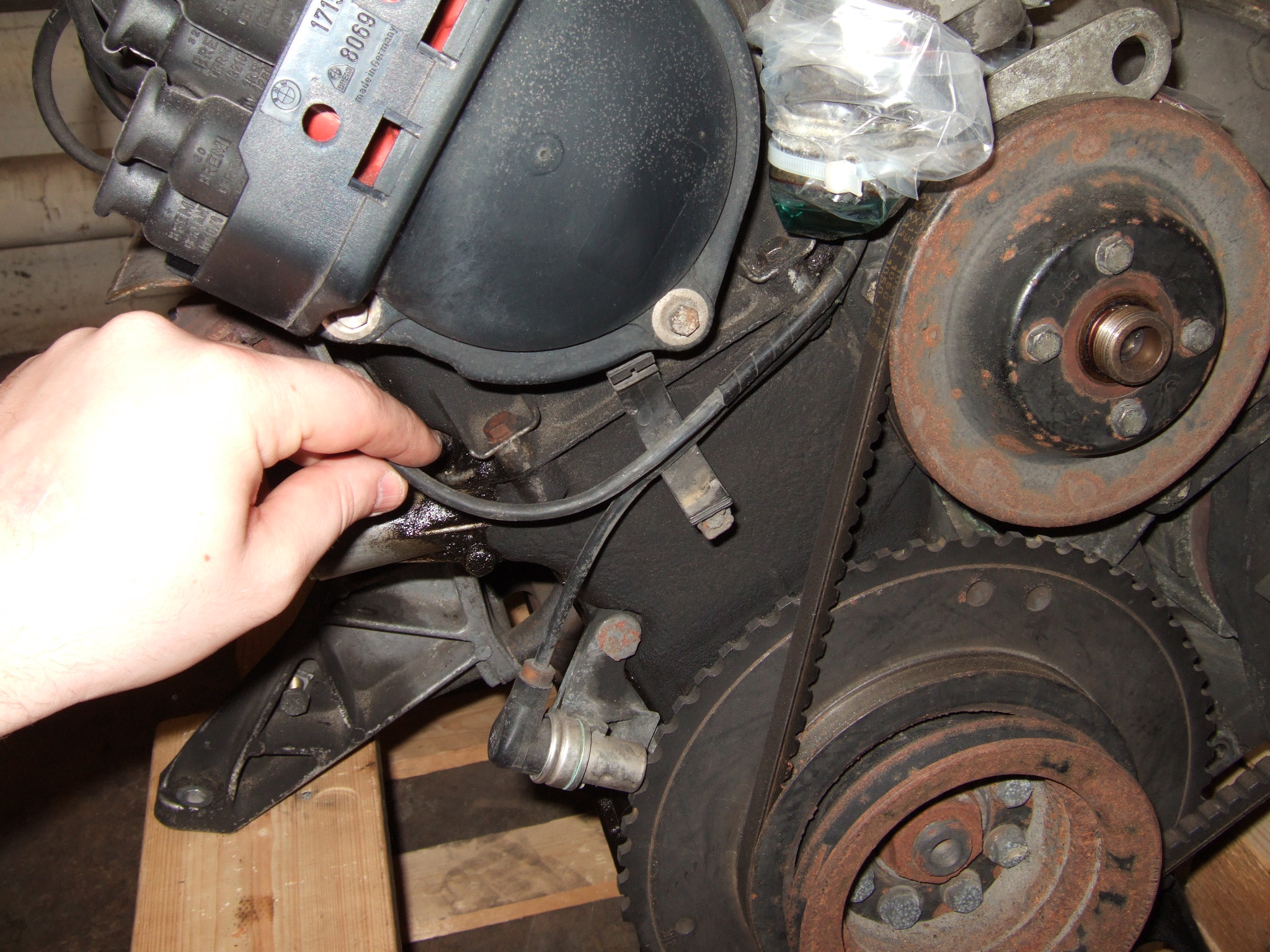
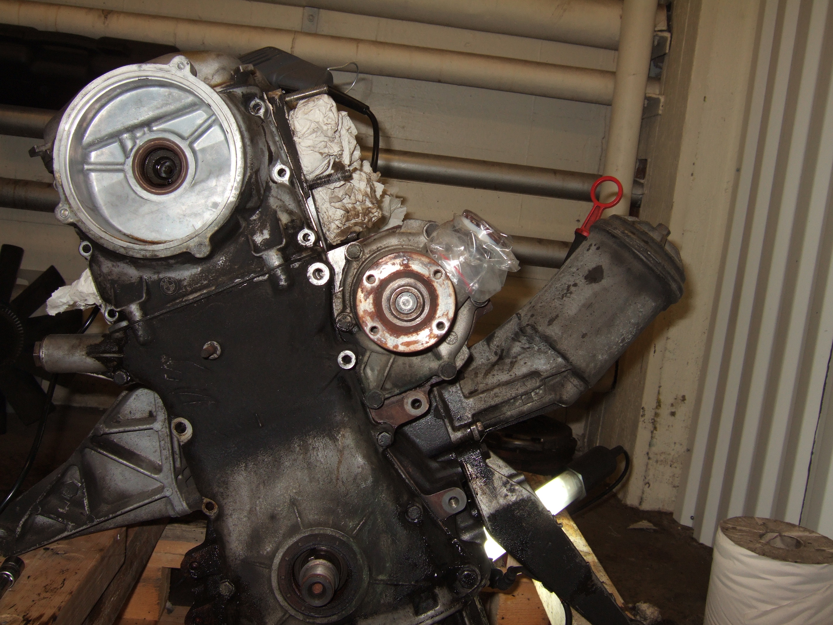
Initially this project was only about replacing a couple of engine and gearbox sels in order to stop the oil leaks. But as the project went along it growed totally out of control (as usually)! Now it is about a total overhaul including near perfect cleanup and refurbishment. So I've added a couple of pictures showing the greasy state of this engine at this point.

Picture 3 : A very filthy engine indeed.
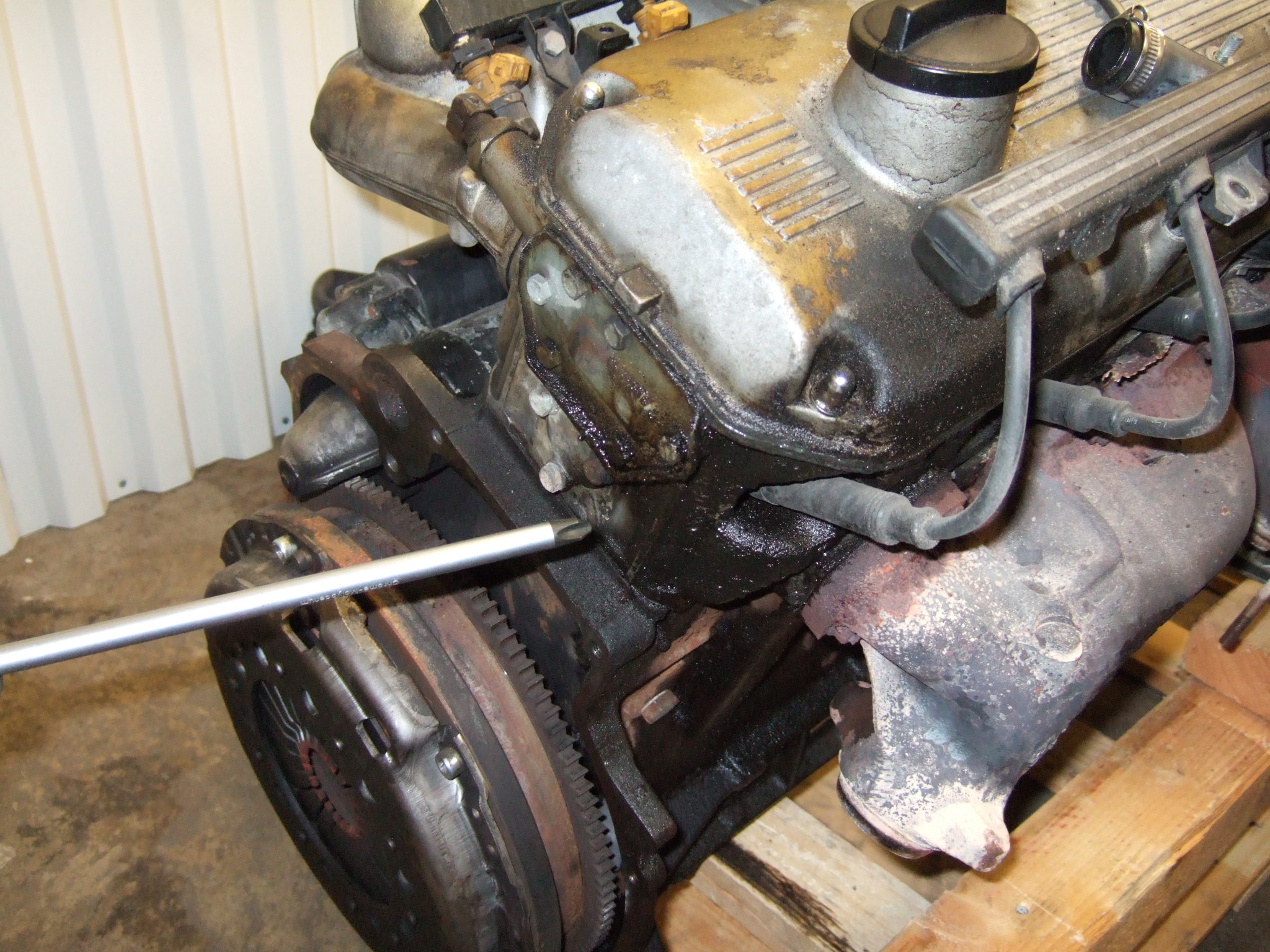
Picture 4 : A very filthy engine indeed.
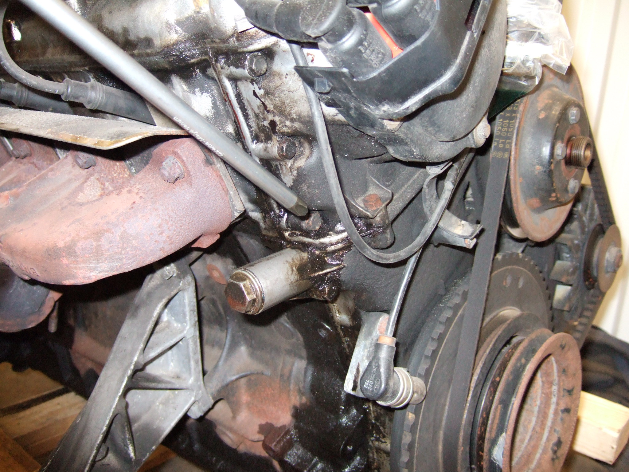
Picture 5 : A very filthy engine indeed.

Picture 6 : A very filthy engine indeed.
Tools, Skills And Parts
The job is very straightforward and does not require any special tools.
Difficulty Level
![]()
The following tools are required for this particular work (tools marked with green checkmark are optional).
| box-end wrench (10 mm) | ||
| box-end wrench (12 mm) (thinwalled) | ||
| box-end wrench (13 mm) | ||
| socket (10 mm) | ||
| socket (12 mm) (long) | ||
| socket (13 mm) | ||
| socket (13 mm) (long) | ||
| socket (17 mm) (1/2") | ||
| socket (19 mm) | ||
| socket extension bar (100 mm) | ||
| socket extension bar (125 mm) (1/2") | ||
| ratchet handle | ||
| breaker bar (460 mm) (1/2") | ||
| hammer | ||
| plumber wrench | ||
| tap (M6-1.00) | ||
| cutting oil | ||
| CRC Penetrating Oil + MoS2 | ||
The following spare parts are required for this particular work (parts marked with green checkmark are optional). Note that the BMW internal numbers are intended for a BMW 535i E34 -89.
| copper nut (exhaust) | 11 62 1 711 954 (12 pcs) | ? SEK | |
| stud (exhaust) | 0712 9 908 134 (12 pcs) | ? SEK | |
| intake manifold gasket | 11 61 1 726 016 (6 pcs) | ? SEK | |
| exhaust manifold gasket | 11 62 1 723 656 (2 pcs) | ? SEK | |
| water pump bolts | 07 11 9 913 712 (6 pcs) | ? SEK |
Removing Ignition Leads
Start by disconnecting all ignition leads from the spark plugs (be gentle and don't pull in the ignition lead - grab the reinforced area close to the spark plug and pull).
If you have removed the engine from the car you have already disconnected the ignition lead from the ignition coil. If not, disconnect it now.
Then continue and disconnect all ignition leads from the distributor. Take one by one and mark them with the cylinder number they are connect to. There is a number casted into the distrubtor at each connector which corresponds to which cylinder the ignition lead is connected to (these numbers can be found on all Bosch original distributors but there are some non-original missing these numbers).

Picture 7 : Disconnect the ignition leads one by one at the distributor and mark them with the cylinder number casted into the distributor.
Next up is to work the "cylinder identification sensor" cable free. It is connected to the cylinder six ignition lead in one end and to the ECU in the other (via the fuel injector harness). So if you have removed the engine from the car you have already disconnected it from the ECU. If not, disconnect it now.
Find the loose connector (somewhere in the middle of the cylinder cover and the intake manifold close to the fuel pressure regulator) and simply backtrace and pullthe cable until it hangs free from the cylinder six ignition lead, see Picture 8 and 9.
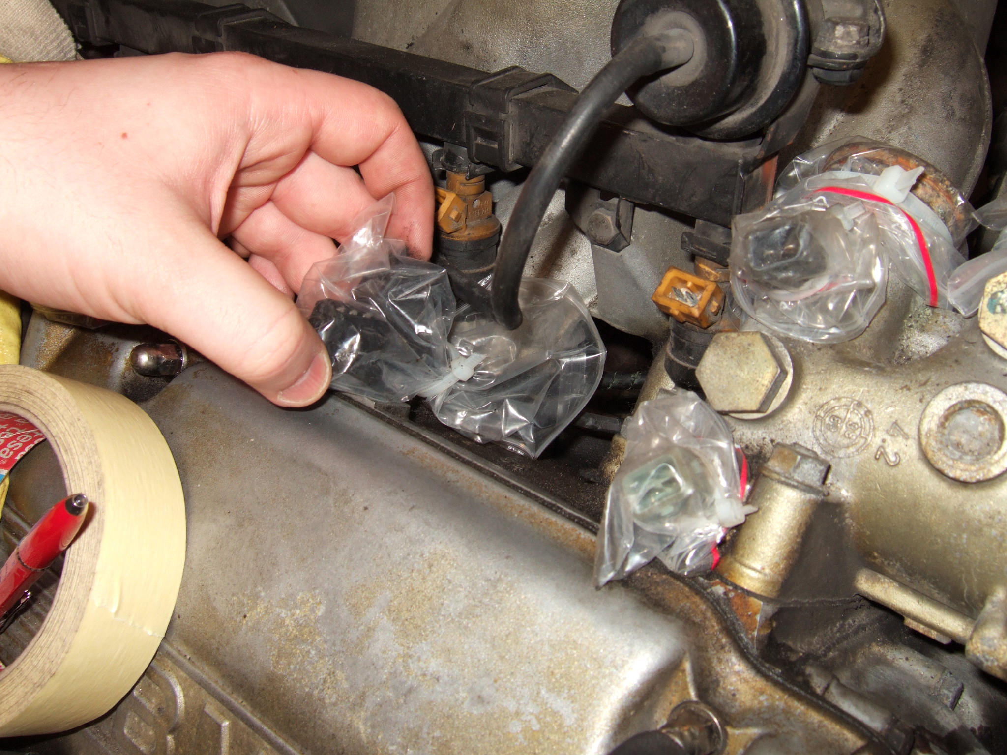
Picture 8 : Find the "cylinder identification sensor" connector located close to the fuel pressure regulator and start to work it free.
Picture 9 : Work the "cylinder identification sensor" cable free by carefully pulling it through all holes until it is completely free.
Now everything is ready to simply lift the entire cable tube straight up as seen in Picture 10. And in Picture 11 you can see how the removed piece of cable tube looks like.

Picture 10 : Simply pull the cable tube straight up to remove it.

Picture 11 : The cable tube containing all the ignition leads and the "cylinder identification sensor" cable which is connected to the cylinder six ignition lead.
Removing Intake Manifold
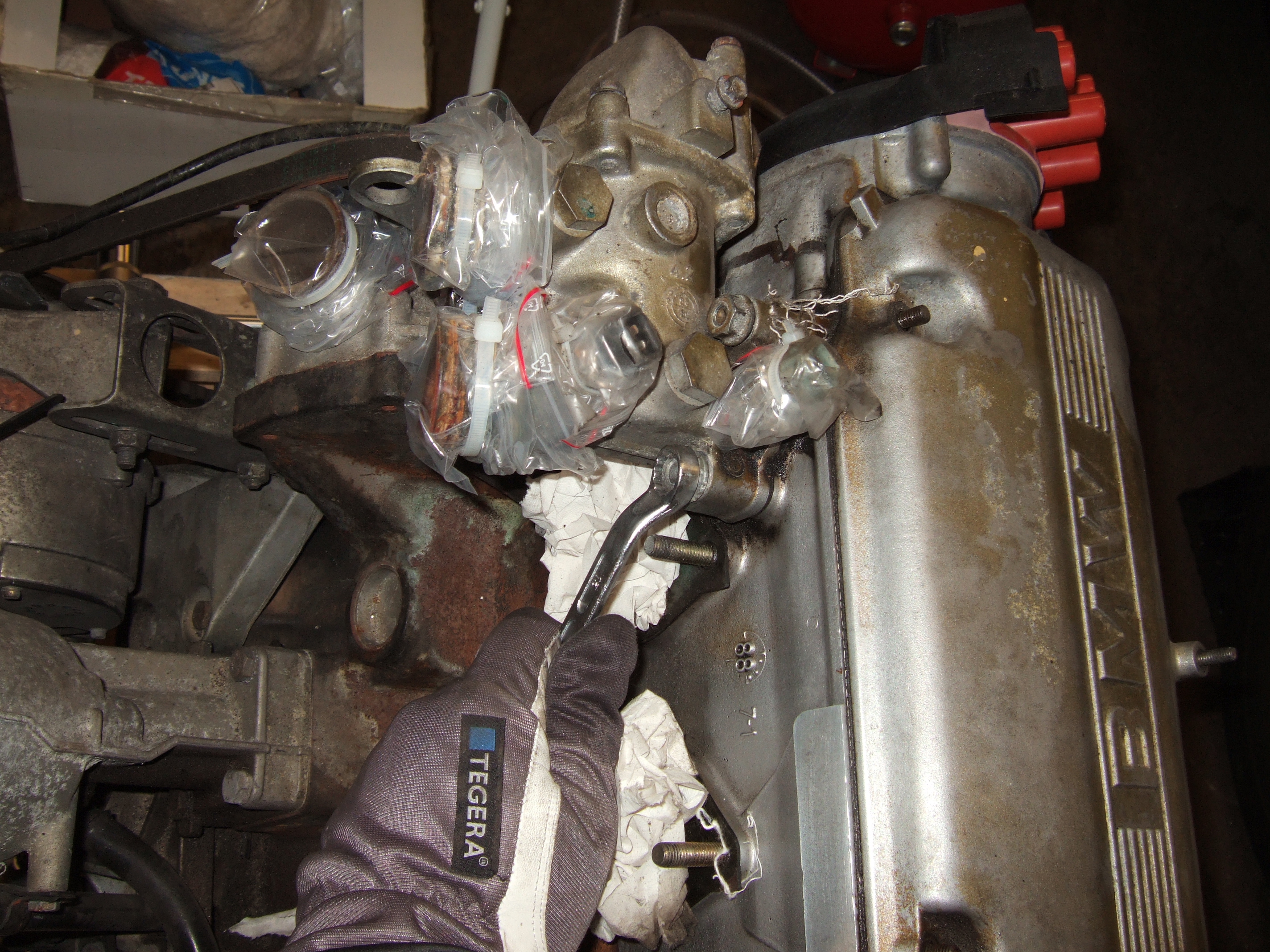
Start by removing the two nuts at each cylinder using a 12 mm box-end wrench. The upper ones are easily accesed (see Picture 12) while the lower ones are a little bit trickier to gain access to (see Picture 13).
By some reason the two nuts for cylinder one was 13 mm on this engine but I haven't got any explanation why except that another kind of nuts where used in any kind of repair long time ago.
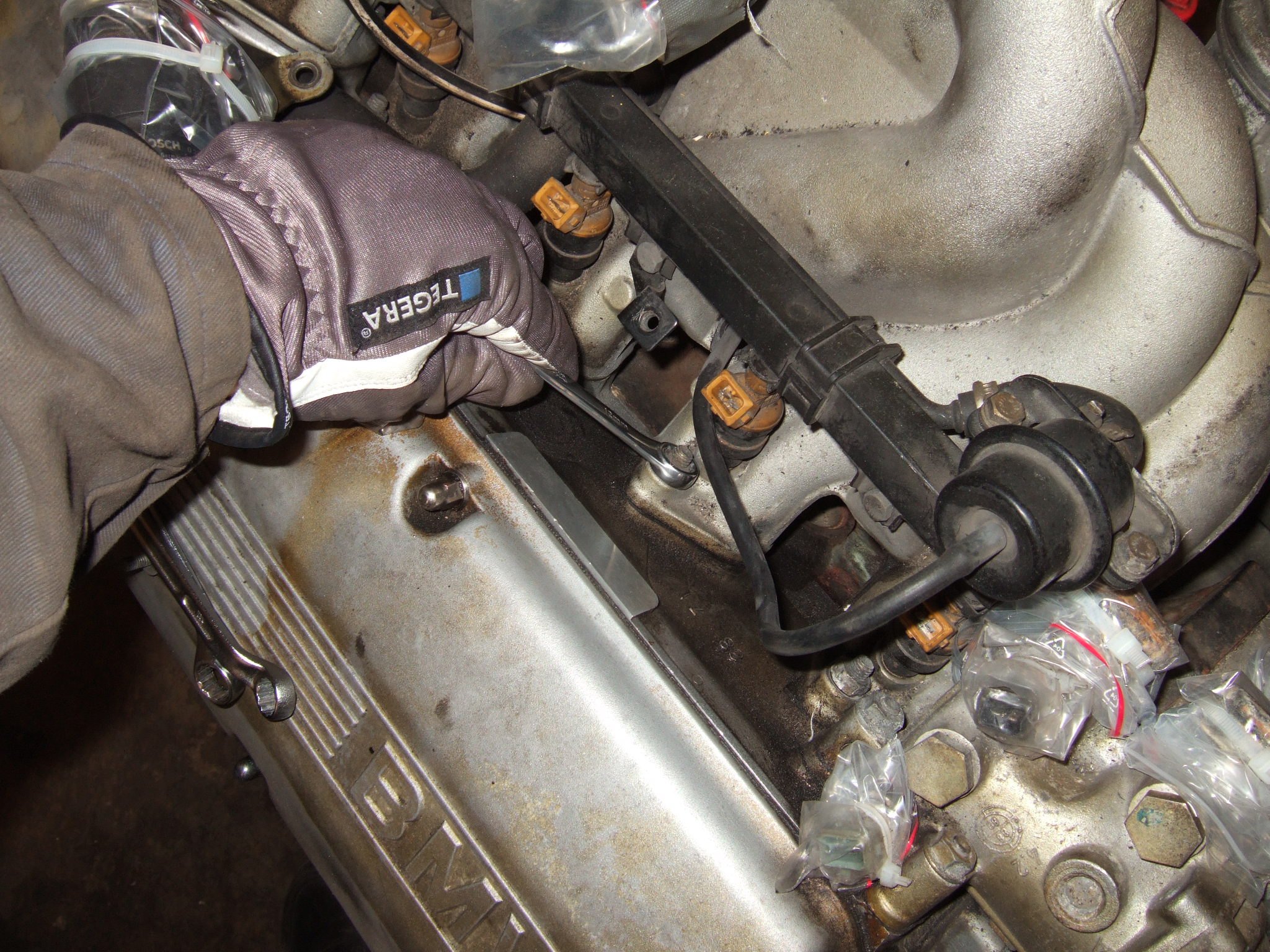
Picture 12 : Removing the intake manifold. The picture shows the removal of the upper 12 mm nut for the cylinder two intake.
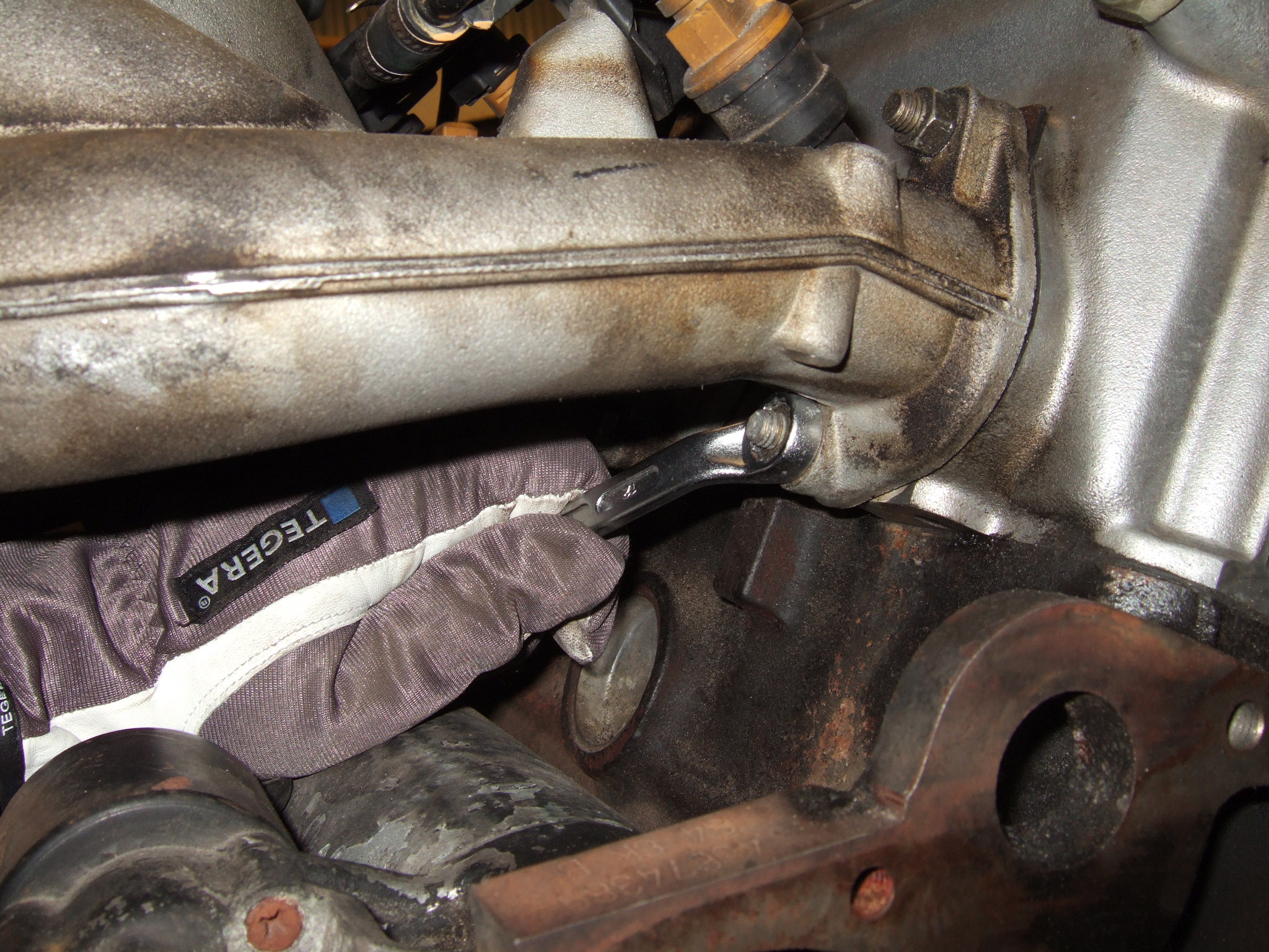
Picture 13 : Removing the intake manifold. The picture shows the removal of the lower 12 mm nut for the cylinder six intake.
Any ordinary box-end wrench will do for the upper nuts but for the lower nuts I found out that a thinwalled box-end wrench was necessary to use due to restricted clearance (See Picture 14).

Picture 14 : Ordinary box-end wrench to the left and a thinwalled box-end wrench to the right (needed for the lower intake manifold nuts).
Next step is to remove the nut from the mounting bracket under the intake manifold. Use a long 13 mm socket and a ratcher handle. Now the intake manifold is completely free and can be removedby pulling it straight out of the cylinder head (see Movie 1).
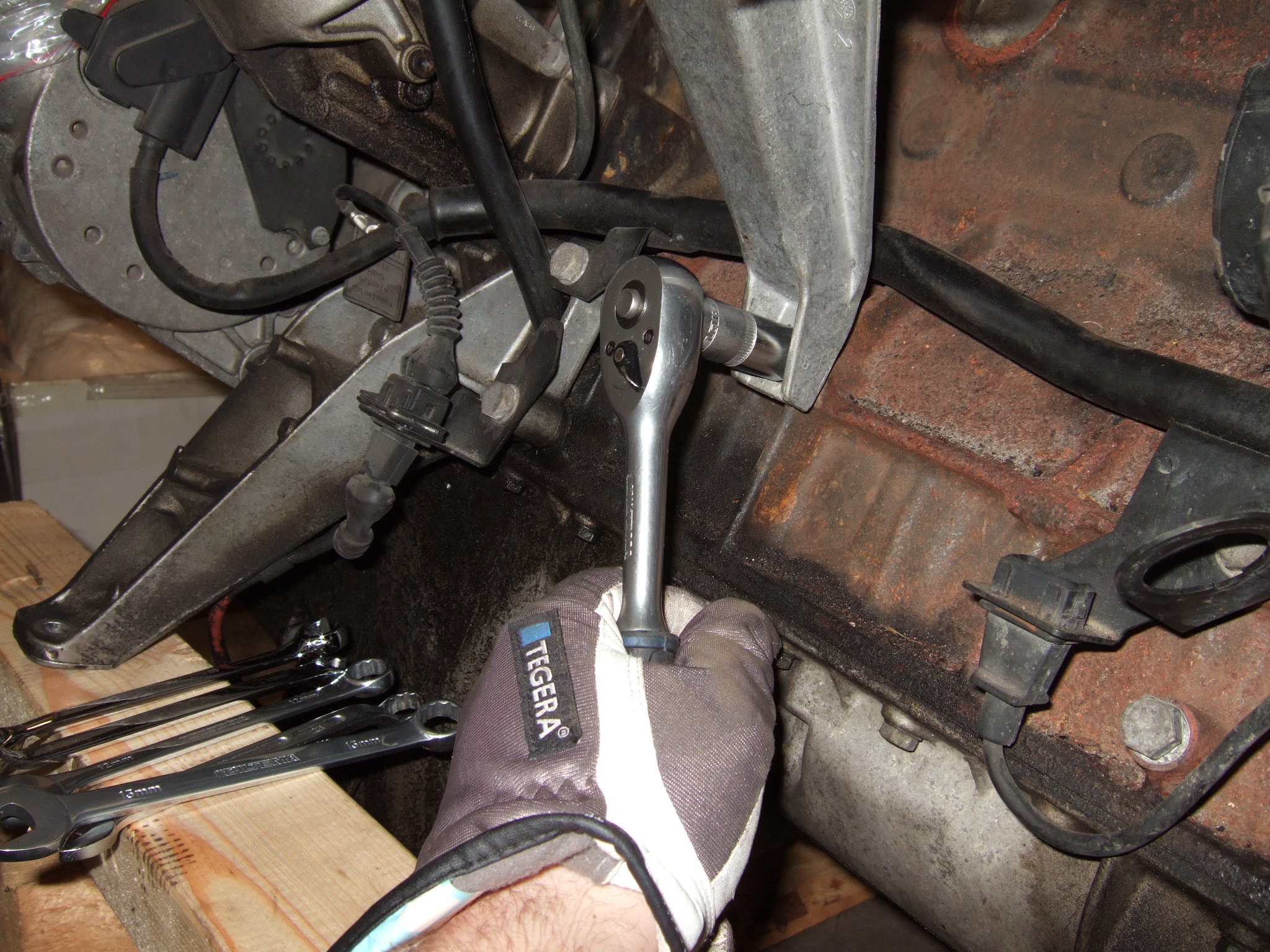
Picture 15: Remove the nut from the mounting bracket under the intake manifold with a long 13 mm socket and a ratchet handle.
Movie 1 : A short clip when removing the intake manifold.
With the intake manifold you can remove the six gaskets. These are reuseable but if your engine have been around for like 10 years and you don't know if they have been replaced or not I recommend to replace them anyway.
And also take the opportunity now when the intake manifold is removed to spend a couple of minutes to admire the view of those fabulous and glorious 47 mm intake valves!

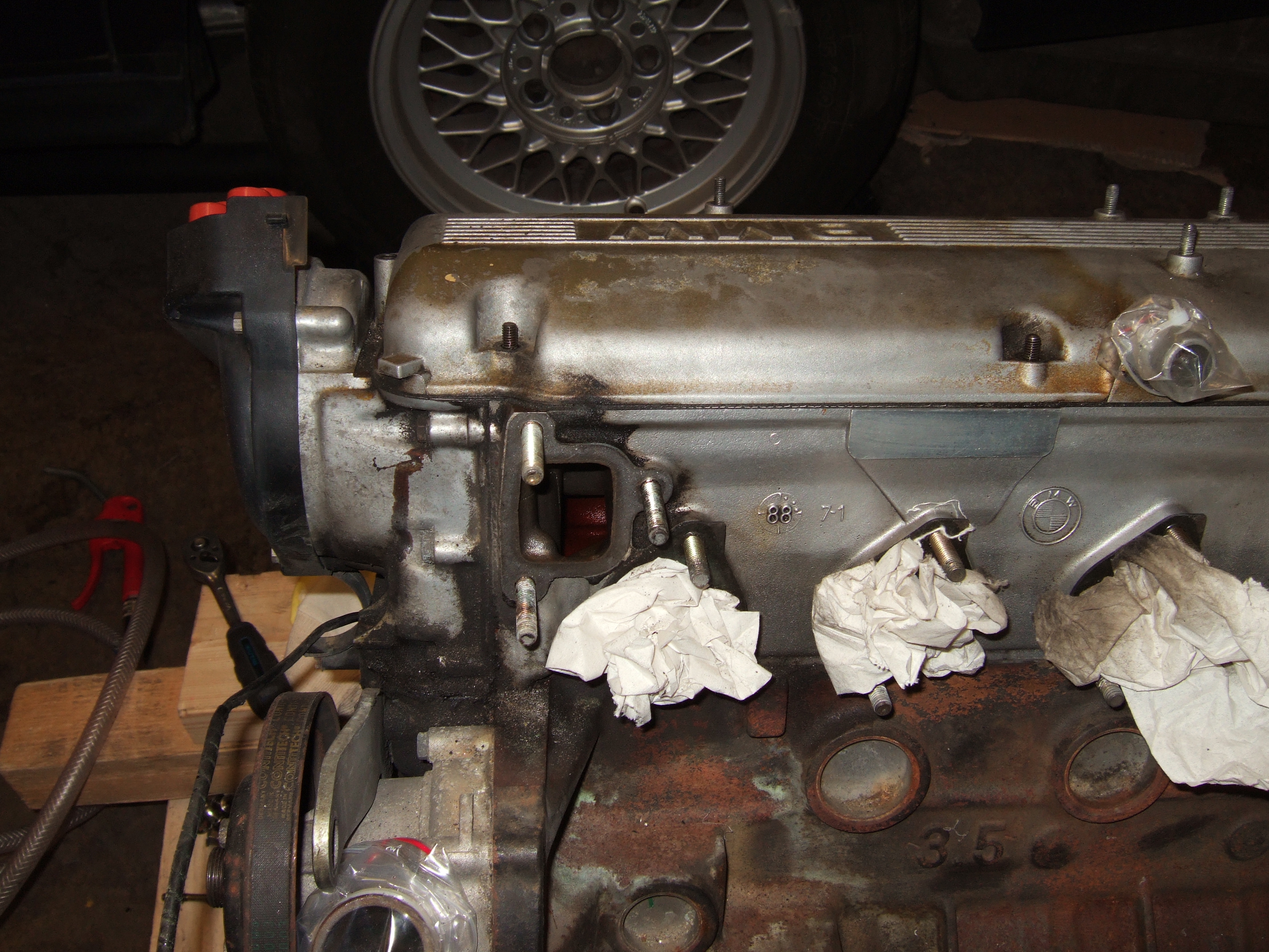
Picture 16 : Engine with intake manifold removed but with the gasket still mounted to the cylinder head.
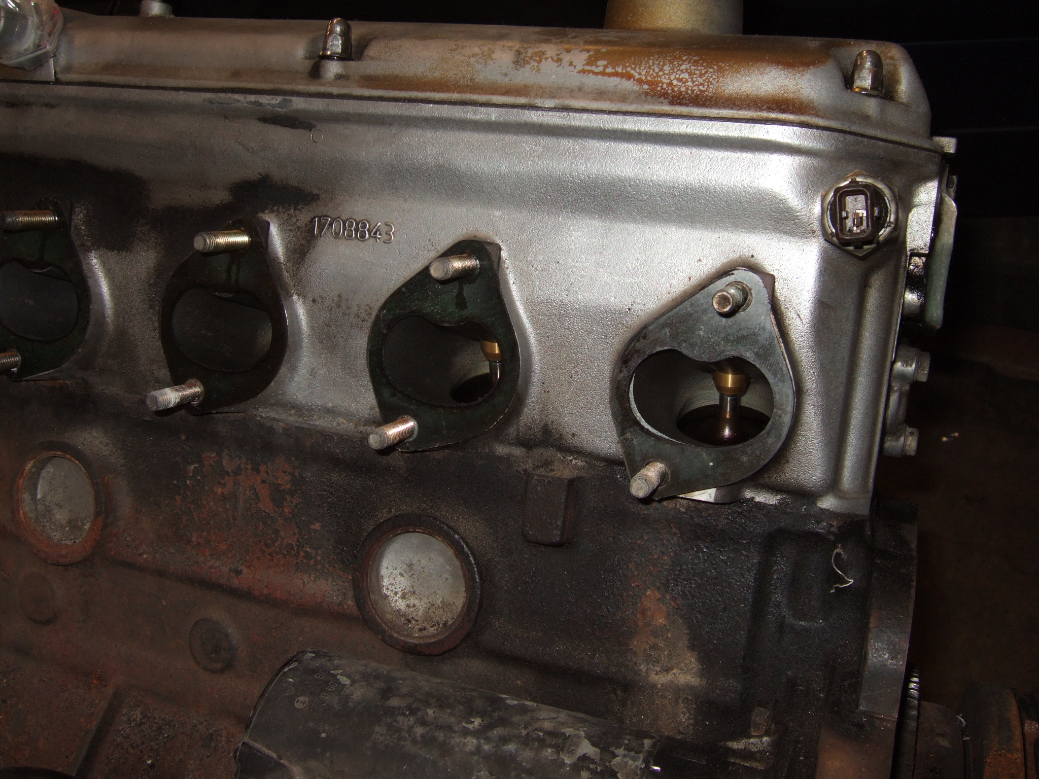
Picture 17 : Engine with intake manifold removed but with the gasket still mounted to the cylinder head.
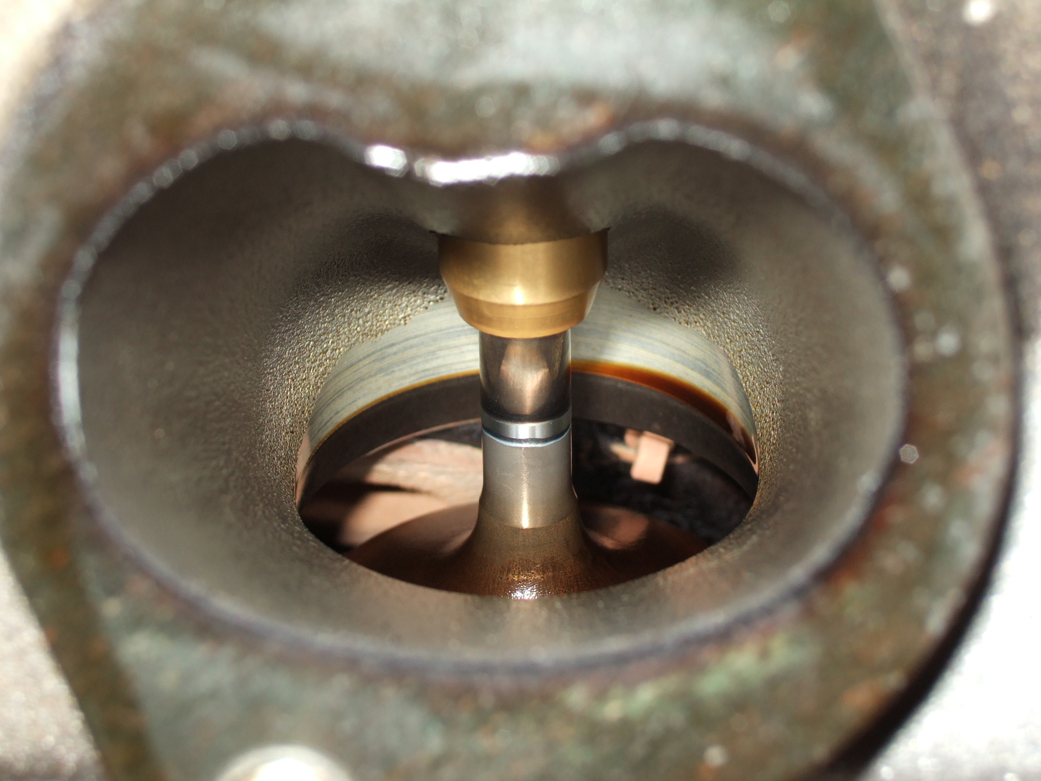
Picture 18 : Behold! The glorious 47 mm intake valve!
Removing Exhaust Manifold
Before trying to remove the exhaust manifolds (there are two - one for cylinder 1-2-3 and one for cylinder 4-5-6) you should spray CRC Penetrating Oil + MoS2 or similar generously over the nuts and studs and let it stay over the night.
The nuts are 12 mm and made of copper so use for example long 12 mm socket and a ratch handle to undo the nuts. Sometimes you will remove the nut only and leaving the stud still attached to the engine block and sometimes the nut is stuck so hard on the stud you will undo the stud and nut as one unit.
It does not matter what because I recommend to replace all the nuts and studs, so all nuts and studs should be removed anyway.
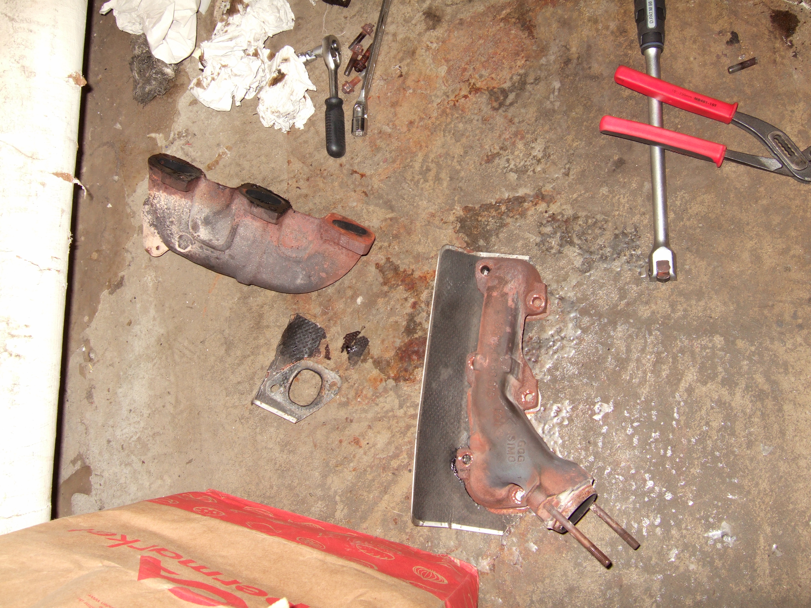
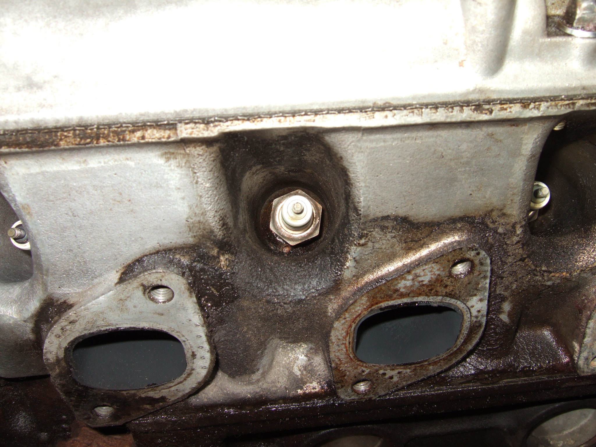
Picture 19 : Both the exhaust manifolds removed.
If there are any studs left in the engine block I can recommend to hit them 10-20 times right on the top of them with a hammer or similar before trying to undo them. This will loosen up the corrosion, if any, in the threads and will make the studs less prone to snap off. Use two nuts on top of each other,plumber wrench or similar to remove the remaining studs in the engine block.
I can also strongly recommend to replace the exhaust manifold gaskets as well (it's actually a combined gasket and heat shield) because they are usually in a terrible state and you have to remove the exhaust manifolds in order to change them and this is usually something you don't do very often so take your chance now and do it.
Picture 20 : Both exhaust manifolds and all studs removed from the engine block.
Picture 21 : This is how dirty and filthy a spark plug hole can be!
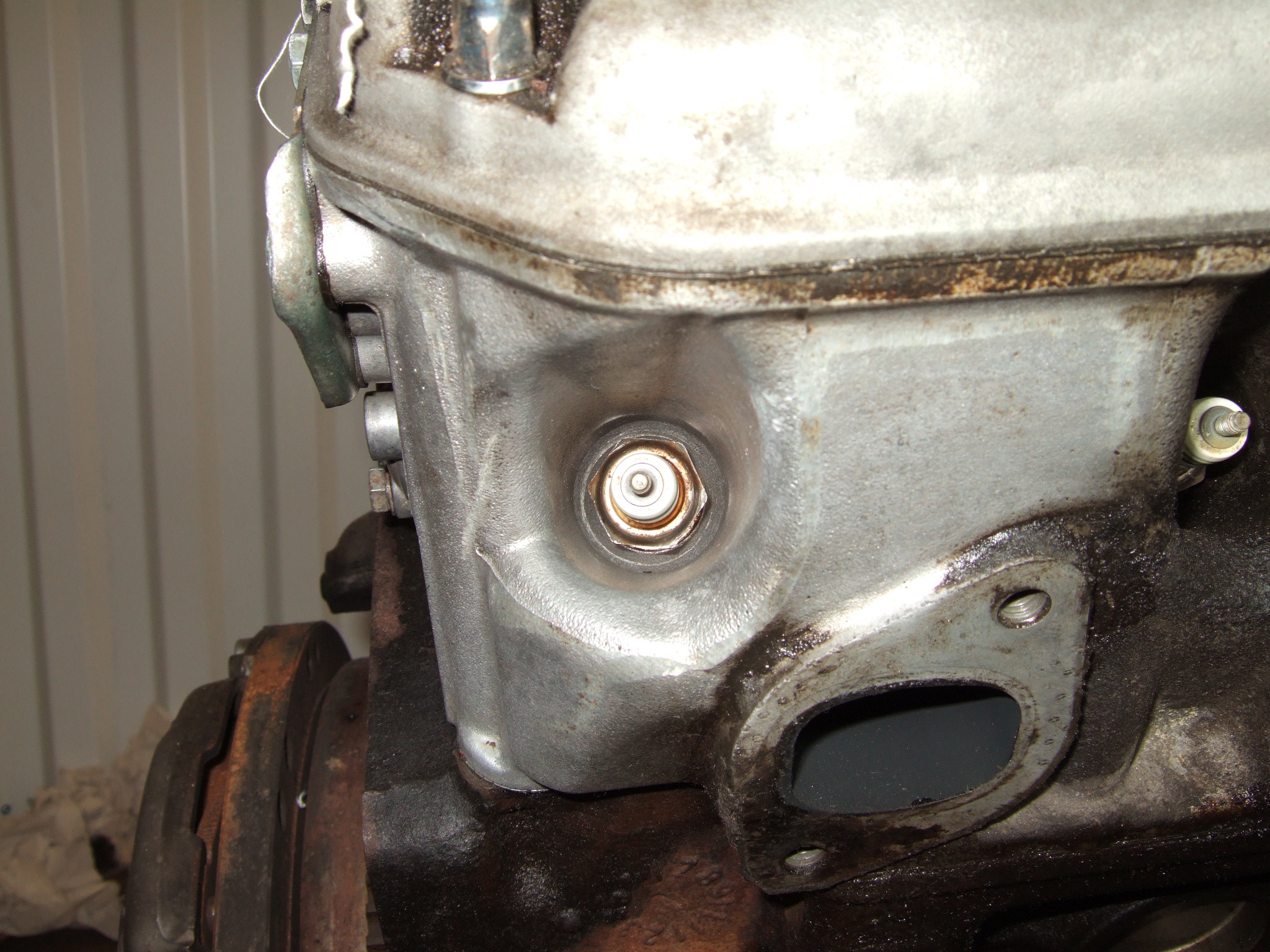
Picture 22 : This is how clean and shiny a spark plug hole will be after some careful cleaning!
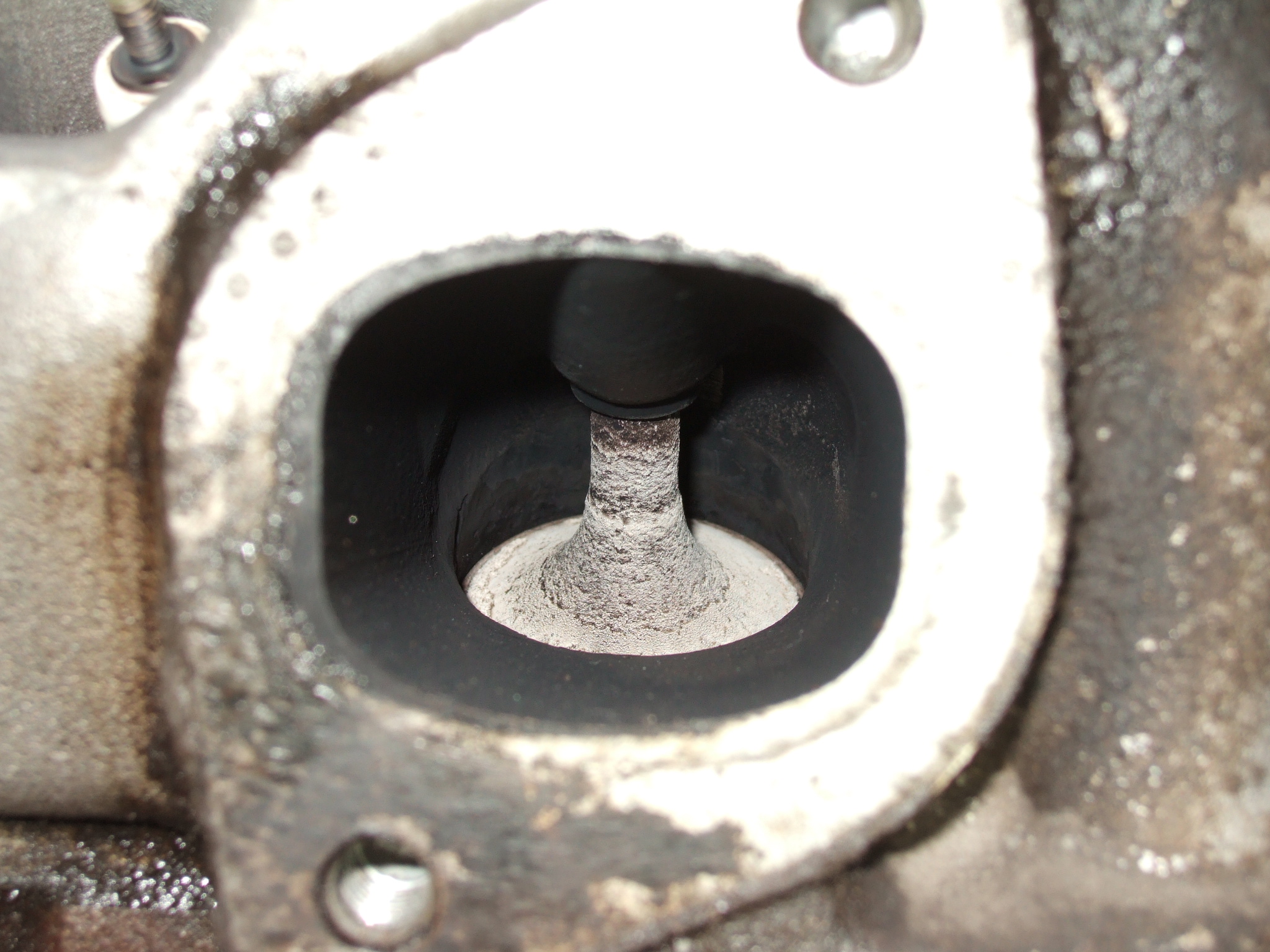
Picture 23 : Nice view on one of the exhaust valves.
Removing Alternator Wiring
We will now disconnect a couple of cables allowing us to remove the alternator as well as the starter motor later on. It will also allow us to remove the metal cable tube (with all cables) running along the left side of the engine block.
Start by localizing the back of the alternator and remove the protecting plastic cover by gently pulling in the flap of the cover.
Picture 24 : The protecting plastic cover at the back of the alternator.
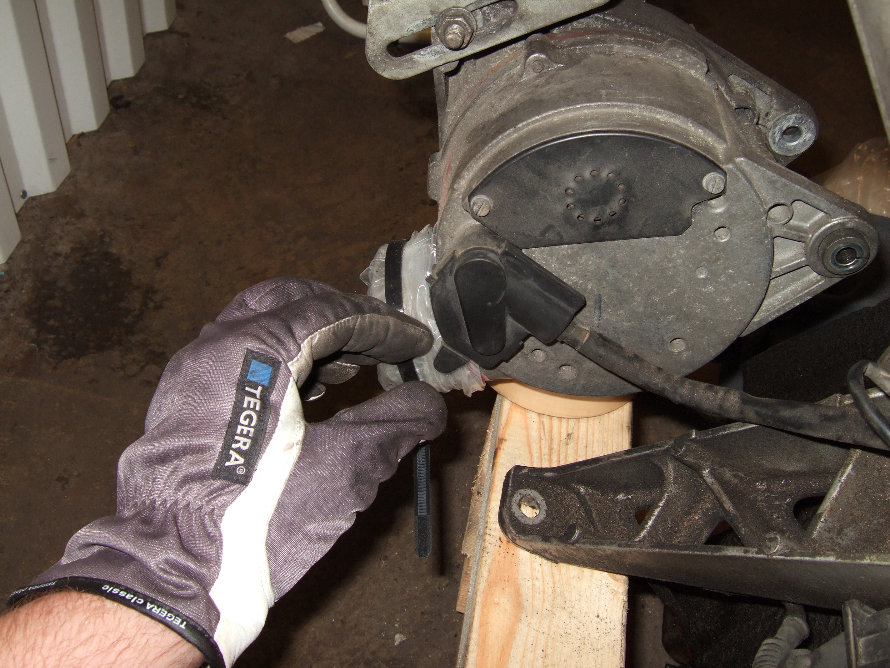
Picture 25 : Remove the protecting plastic cover by pulling in the flap.
Behind the protecting plastic cover you will find two cables attached with one collar nut each. Use a 10 mm and 13 mm socket and a ratchet handle to remove the nuts, then remove the cables and finally reinstall the nuts again.
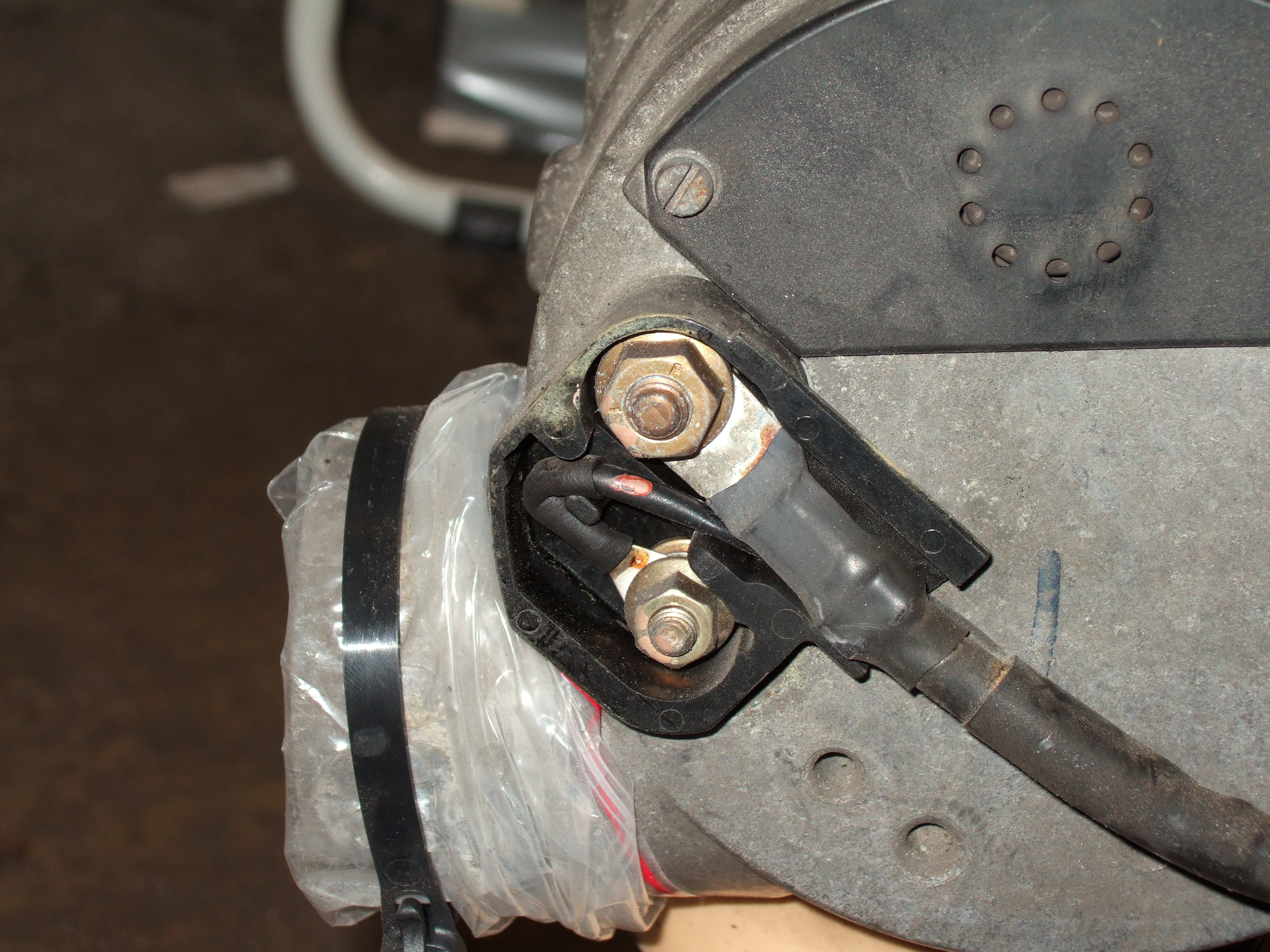
Picture 26 : Alternator cables attached with 10 and 13 mm collar nuts.
Next disconnect the oil level sensor connector.
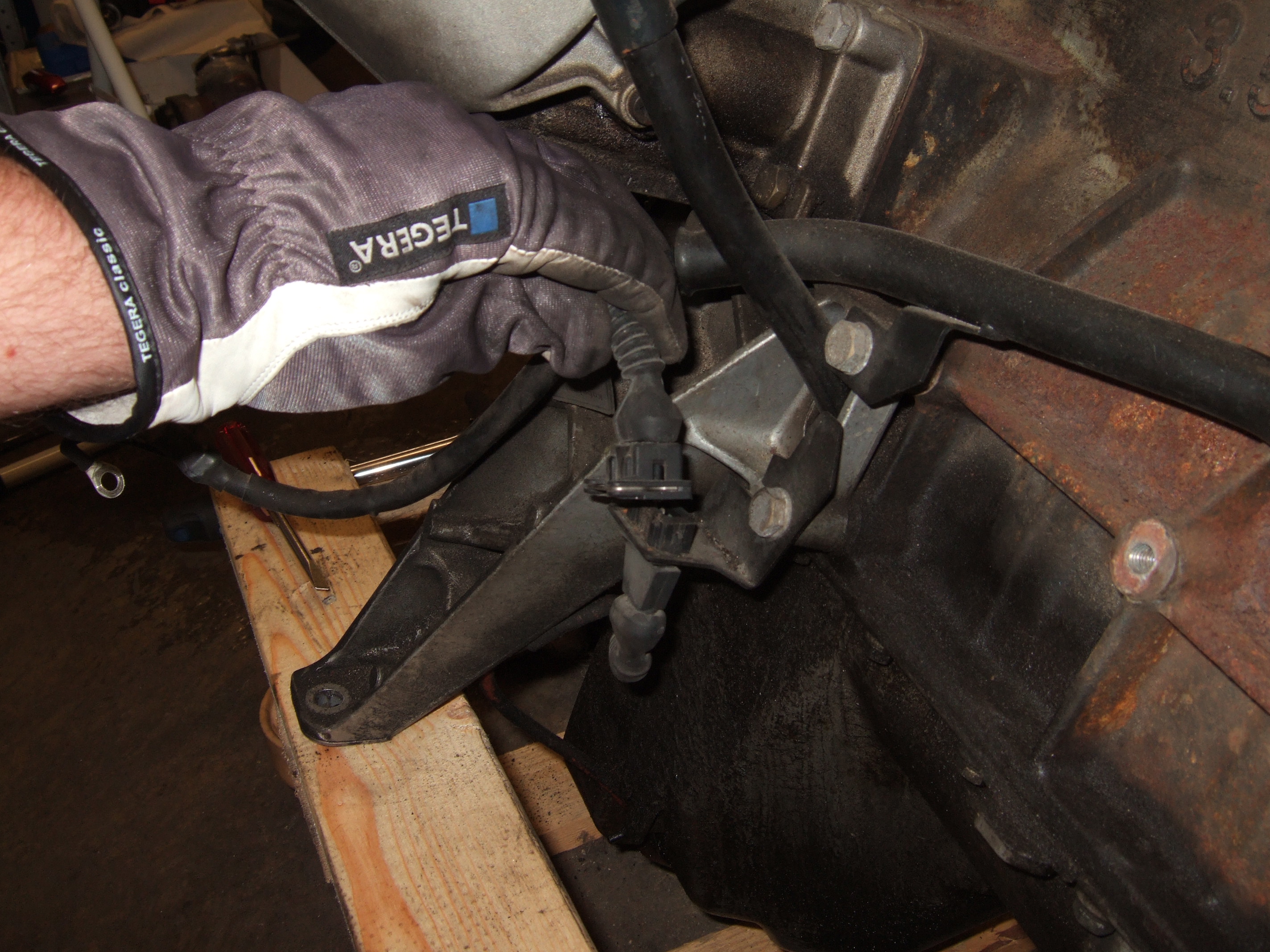
Picture 27 : Disconnect the oil level sensor connector.
Disconnect the cable attached to the starter motor solenoid. Use a long 13 mm socket and a ratchet handle to remove the collar nut, then remove the cable and finally reinstall the nut again.

Picture 28 : Starter motor solenoid cable attached with a 13 mm collar nut.
Now the alternator and the starter motor is completely free to remove (which we will do in the nextcoming steps).And the metal cable tube (with cables) is attached to the engine block with only two 13 mm screws so this will be removed now.
Simply undo the two 13 mm screws holding the metal cable tube in place using a 13 mm socket, a 100 mm socket extension bar and a ratchet handle and then simply remove the entire unit (the metal tube and cables in one piece).
Picture 29 : The metal cable tube attached to the engine block with two 13 mm screws.
Removing Alternator
The alternator has two mounting points. It pivots around a bolt at the bottom and at the top there is a toothed-rack mechanism. This mechanism is used to adjust the tension of the V-belt driving both the alternator and the water pump.
To remove the V-belt (so we can remove the alternator, water pump and the crankshaft pulleys) we need to first remove the tension of the V-belt. Start by loosening the bolt at the bottom which the alternator pivots around. Both bolt and nut are 10 mm (just loosening it - not needed to remove it completely at this stage) - see Picture 30.
Picture 30 : The pivot bolt at the bottom of the alternator.
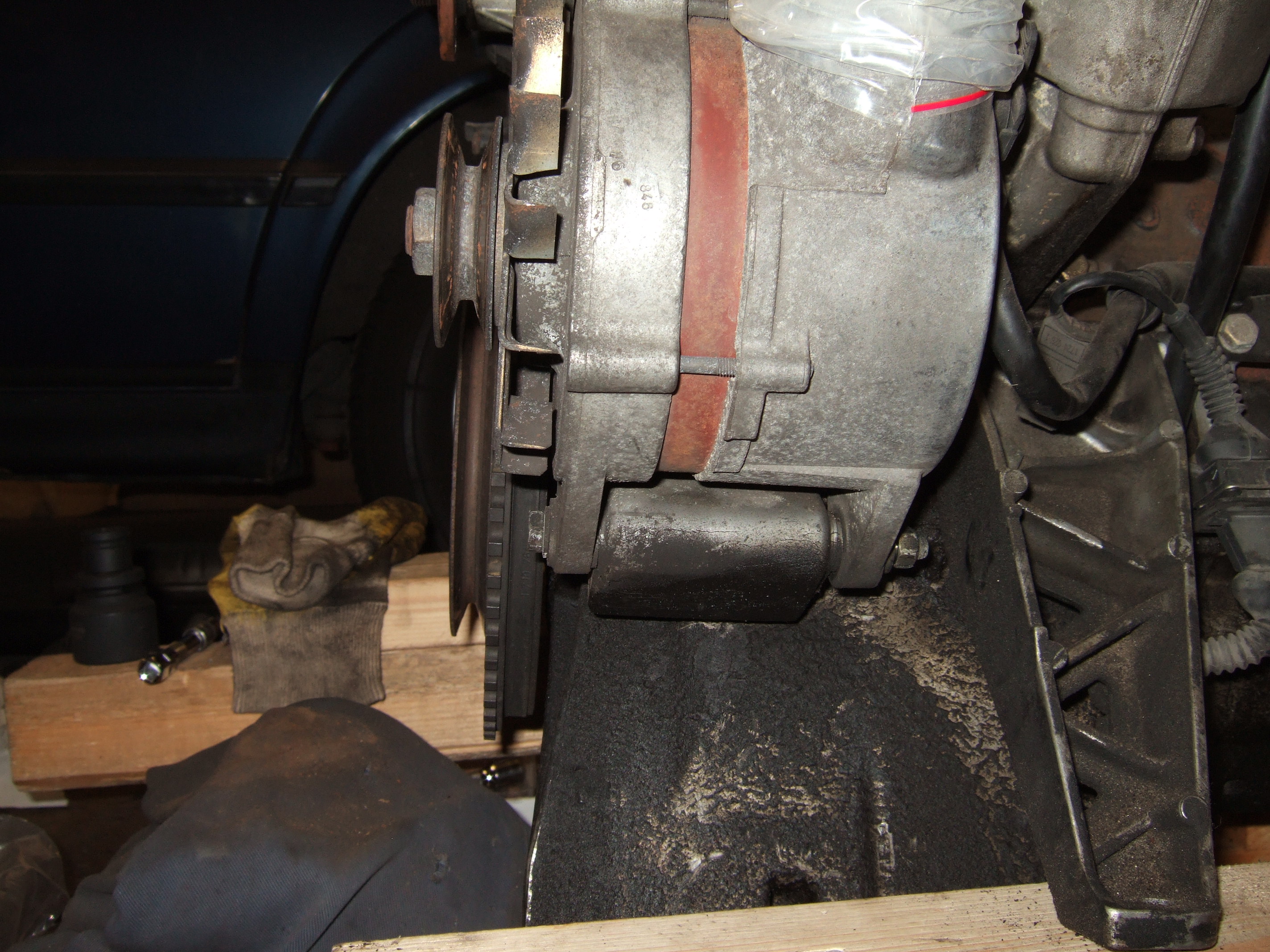
Now we can remove the tension of the V-belt. The adjustment bolt is at the top of the alternator and has a 19 mm hex head with some small cogs under the head and is locked in place by a 13 mm hex head nut at the other end (see Picture 31). So start by loosening (not removing) the 13 mm hex head nut. Now you turn the 19 mm heax head adjustment bolt anti-clockwise to provide less tension on the V-belt. Simply turn the adjustment bolt clockwise until you can remove the V-belt without problems.

Picture 31 : The adjustment bolt (19 mm hex head bolt and 13 mm nut) on the toothed-rack mechanism at the alternator.
With the V-belt removed we can now remove the alternator completely. We will remove the alternator and the toothed-rack mechanism in one piece. Start by removed the bolt holding the toothed-rack mechanism and mounting plate together. It is a 13 mm hex head bolt and a 13 mm nut - see Picture 32.
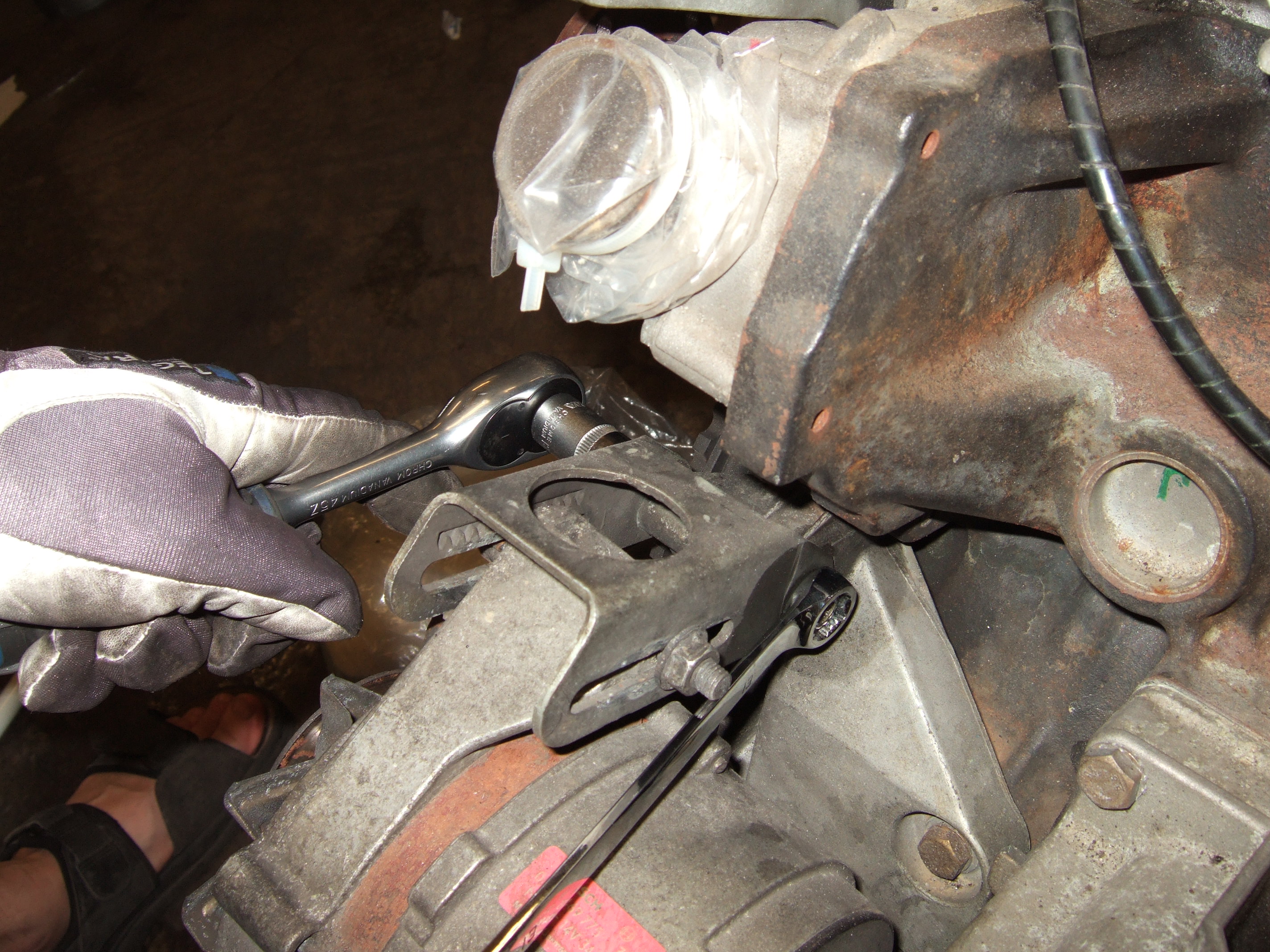
Picture 32 : Undo the bolt and nut which holds the toothed-rack mechanism and the mounting plate together.
With the toothed-rack mechanism deattached from the mounting plate you can now swing out the alternator around the pivot bolt as seen in Picture 33. Last step is simply to remove this pivot bolt completelt and the alternator can be removed.
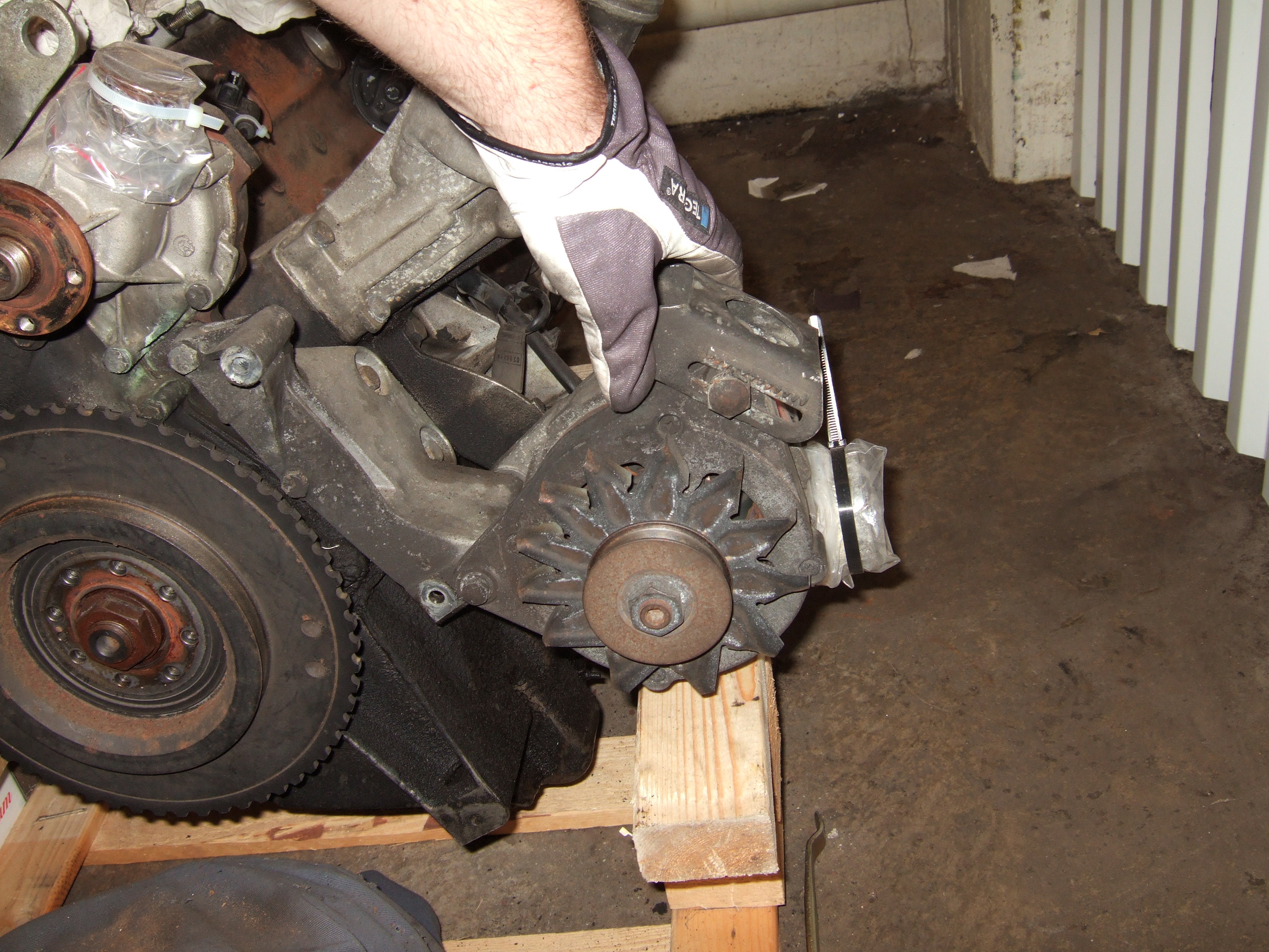
Picture 33 : With the toothed-rack mechanism deattached the alternator swings freely around the pivot bolt.
As a final touch we will remove the mounting plate as well from the engine block. It is attached with two 13 mm hex head bolts at the side of the engine block and two 13 mm hex head bolts on the front of the engine block. Note there is a washer between each bolt and mounting plate.

Picture 34 : Alternator mounting plate attached to the engine block with in total four 13 mm hex head bolts.
Removing Starter Motor
With the engine removed from the car and the intake manifold removed as well, this item is quite easy to remove. However be aware the the nuts may need some force to break loose so some heavy-duty tools are recommended.
The starter motor is attached to the engine block with two 17 mm hex head bolts. Use for example a 1/2" 17 mm socket together with a 125 mm socket extension bar and a 460 mm breaker bar.

Picture 35 : The starter motor is attached to the engine block with two 17 mm hex head bolts and may need some force to break loose.
Removing Thermostat Housing
Attached to the cylinder head with three 13 mm hex head bolts (two at the top and one at the bottom). Use for example a 13 mm box-end wrench or similar to remove the bolts. When all three bolts have been removed you can remove the thermostat housing by simply pulling it straight out.
Picture 36 : Thermostat housing attached to the cylinder head with three 13 mm hex head bolts (two at the top and one at the bottom).

Picture 37 : Thermostat housing attached to the cylinder head with three 13 mm hex head bolts (two at the top and one at the bottom).
Picture 38 : The thermostat housing removed from the cylinder head.
Removing Water Pump
The water pump is attached to the engine block with six 10 mm hex head bolts (three at the top and three at the bottom). All the bolts have the same length so there is no risk of mixing them up.
Picture 39 : The water pump attached to the engine block with six 10 mm hex head bolts.
Both the bolts and threads were in a terrible condition so a new set of bolts are highly recommended. I can also recommend to recut the threads using a M6-1.00 tap and some cutting oil.
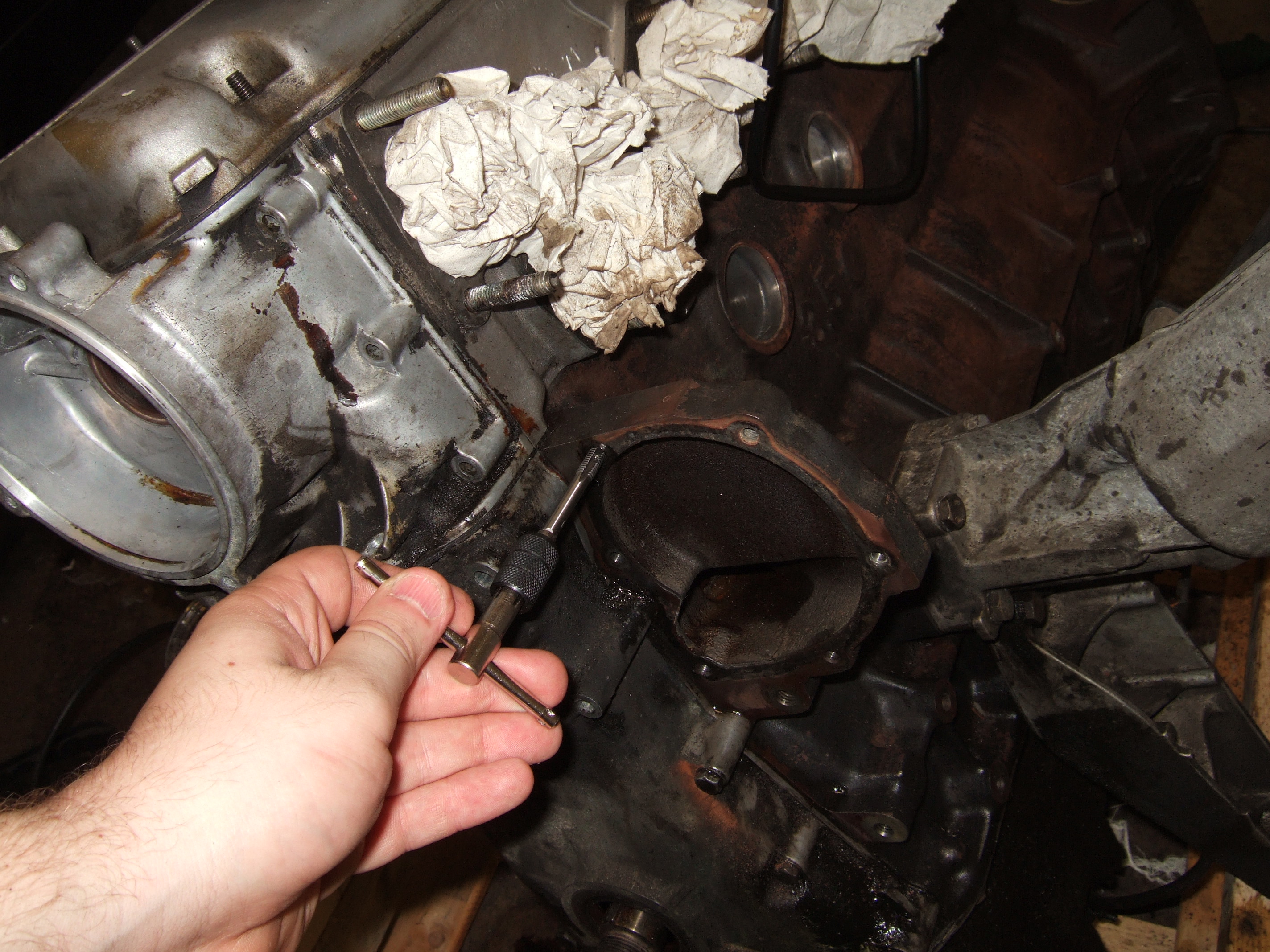
Picture 40 : Recutting the threads using a M6-1.00 tap and some cutting oil.