| |
||
Tools, Skills And PartsThe job is fairly straightforward as long as you are not in a hurry and have the correc tools. Difficulty Level
The following tools are required for this particular work (tools marked with green checkmark are optional).
The following spare parts are required for this particular work (parts marked with green checkmark are optional). Note that the BMW internal numbers are intended for a BMW 535i E34 -89.
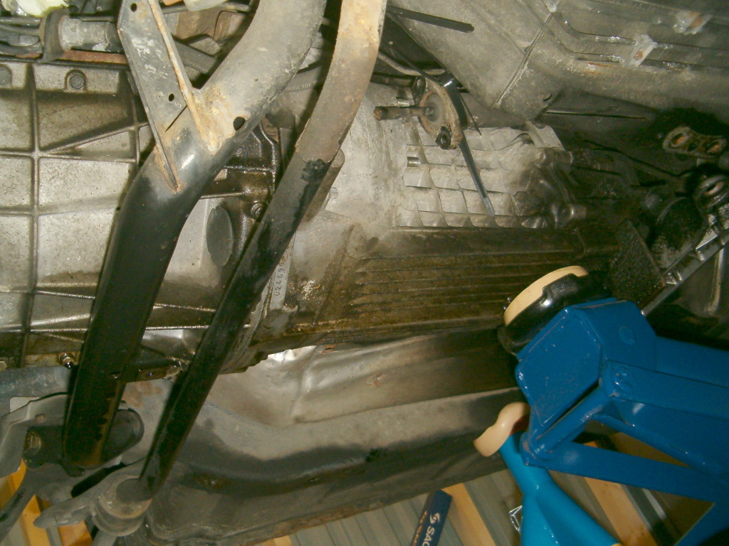
Removing GearboxFirst start by putting in 5:th gear - since we later on will replace the selector shaft oil seal. Otherwise it is not necessary to do so. Then disconnect harness connector from reverse light switch located on the right side of the gearbox. Step 1 : Unbolt Clutch Slave Cylinder The clutch slave cylinder must be unbolted from the gearbox. Note that you do not have to separate any hydraulics pipes or hoses in order to remove the gearbox. 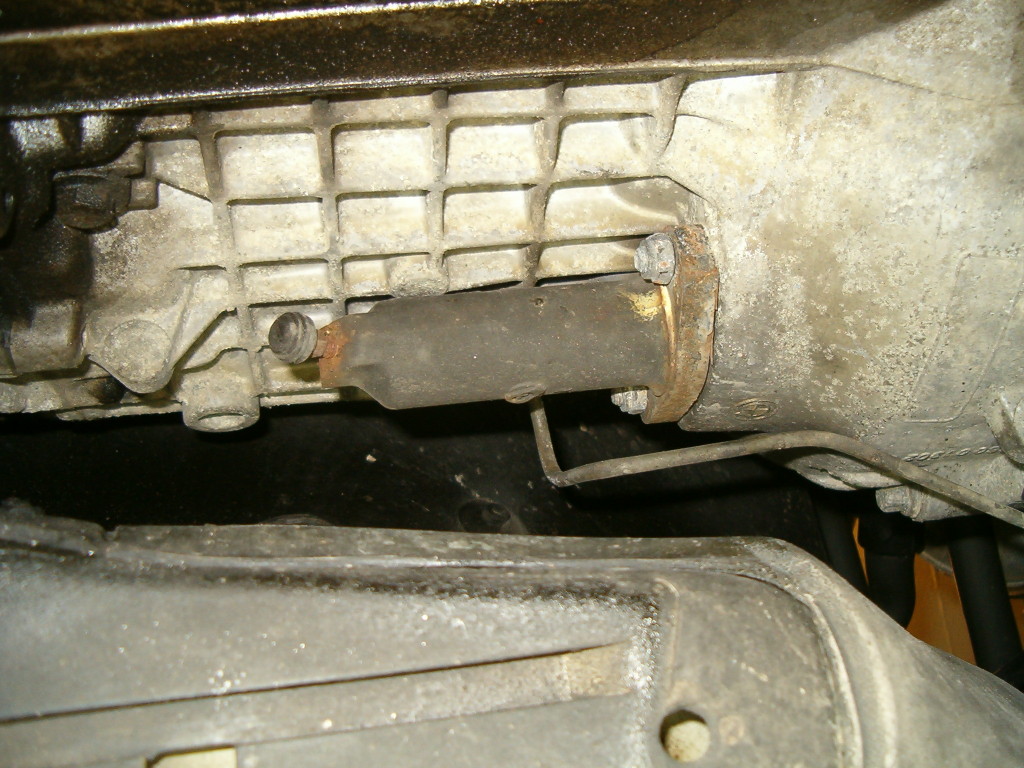 The clutch slave cylinder is bolted to the gearbox with two self-locking 13 mm hex head nuts (see red arrows). Undo the two 13 mm hex head nuts. Recommended to use a 13 mm socket and a ratchet handle for the lower one and then add a 100 mm socket extension bar to be able to remove the upper one. It's self-locking nut so they should not be used again. Do not let the clutch slave cylinder hang in the hydraulic pipe - support it using a stiff wire or similar. Step 2 : Remove Gear Shift Linkage Next step is to remove some of the gear shift linkage to separate the gearbox from the chassis. Below you can see an exploded view of the main components in the gear shift linkage.  Exploded view over the gear linkage. Only parts interested in this operation are numbered. We will start by removing the selector rod (#11). It is secured by a locking plate at both the gearbox and the shift lever end. Use a retaining ring plier to remove the one at the gearbox (and then simply slide out the selector rod end from the bushing). Then remove the one at the shift lever. 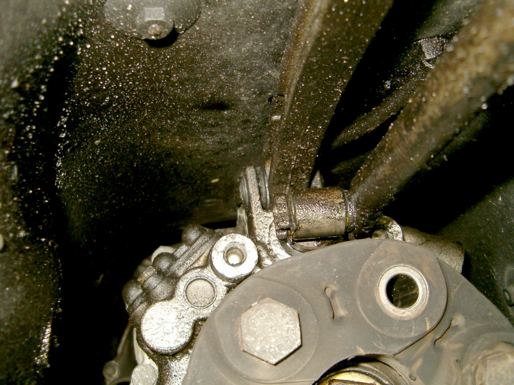 The selector rod secured with a locking plate (#17) at the gearbox end (see red arrow). 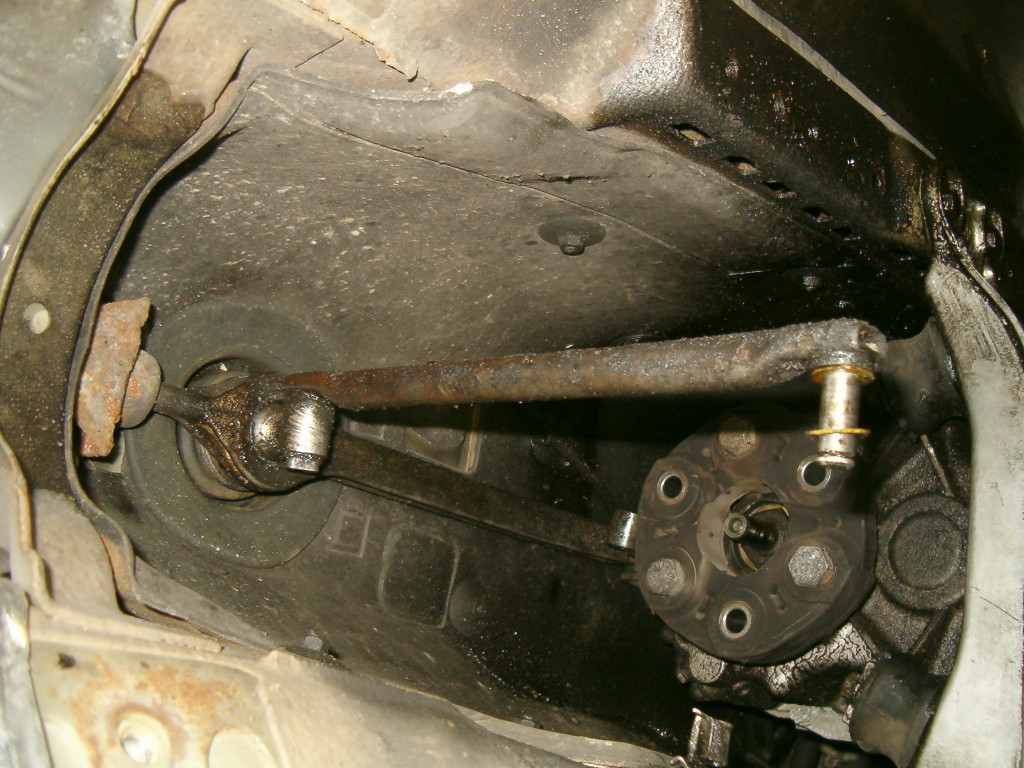 The selector rod secured with a locking plate (#13) at the shift lever (#6) end (see red arrow). Next we will remove the shifting arm (#1). Remove the bracket (#4) completely by first removing the 13 mm hex head nut (#5) on the other side and then unhinge it from the chassis. Last step is to separate the shifting arm (#1) from the shift lever (#6). This is made by turning the shift lever bearing (#7) 90 degrees clockwise and push up the bearing and the shift lever from the shifting arm. There are special tool for this but a good needle nose pliers will do the work as well. 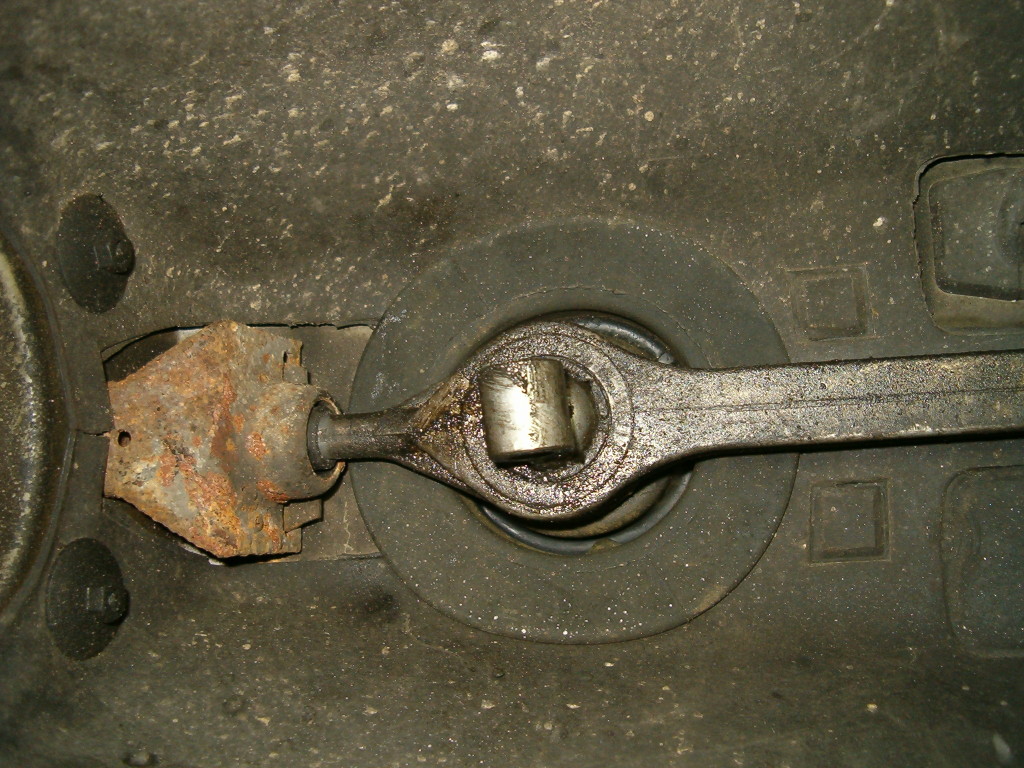 The shift lever bearing (#7) pointed out by the blue arrow shall be turned 90 degress clockwise as indicated by the red arrow to separate the shift lever and the shifting arm. Step 3 : Unbolt And Remove The Gearbox Before you start unbolt you must lower the entire engine+gearbox package. There is no way you can reach all Torx screws without lowering it first. So place a large and very stable floor jack under the gearbox (use a jack-pad or similar between the floor jack and the gearbox). Place the floor jack where the longitudinal mass centrum of the gearbox is. And it is not in the middle (all the cogs and shafts are located in the middle and end of the gearbox). Place it as in the pictures below and you will have a good balance once you are about to separate and lower the gearbox. Having a good balance helps a lot if you are alone doing this job. Raise the floor jack until the feel it supports the gearbox as much as the transmission cross member at the rear of the gearbox. Now remove all four 13 mm hex head screws holding the transmission cross member in place. Don't remove the transmission cross member since it is a good piece to use when it comes to maneuver the gearbox later on. 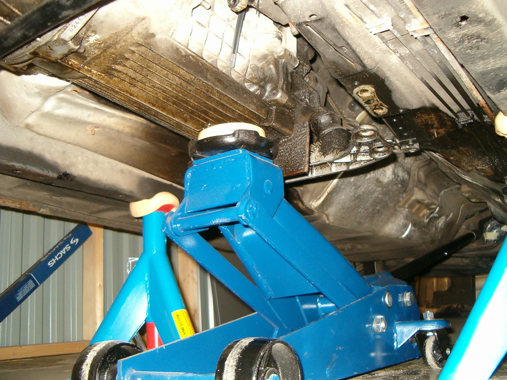 Place your largest floor jack under the gearbox (roughly at the longitudinal mass centrum). |
 Lower the engine+gearbox package until the engine block rests on the front cross member. Lower the gearbox very carefully. Lower one bit at a time, take a look around the gearbox and the engine compartment between each time to verify nothing is jammed or crushed. Keep an extra eye on the clutch slave cylinder when you are lowering the gearbox. The goal is to lower it until the engine block rests on the front cross member. 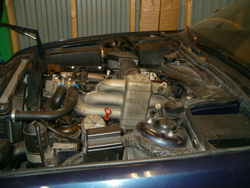 You can see the engine is slightly tilted backwards after we have lowered the engine+gearbox package. There are in total 11 Torx screws holding the engine and gearbox together. They are all different in size and length (well not completely but it feels like that). So below you have a picture pointing out the location and also the size of the head for each Torx screw. Note! It seems that later 535i were equipped with a slightly different Getrag 260/6 gearbox where the two bosses marked B and D have been removed. This means that the bottom M8x60 bolts suddenly bottoms out and you should have a M8x50 instead. Therefor I recommend to start at a specific screw, remove it, place it in a marked zip bag, move to next screw found when moving in a clockwise (or anti-clockwise) movement and repeat the procedure. 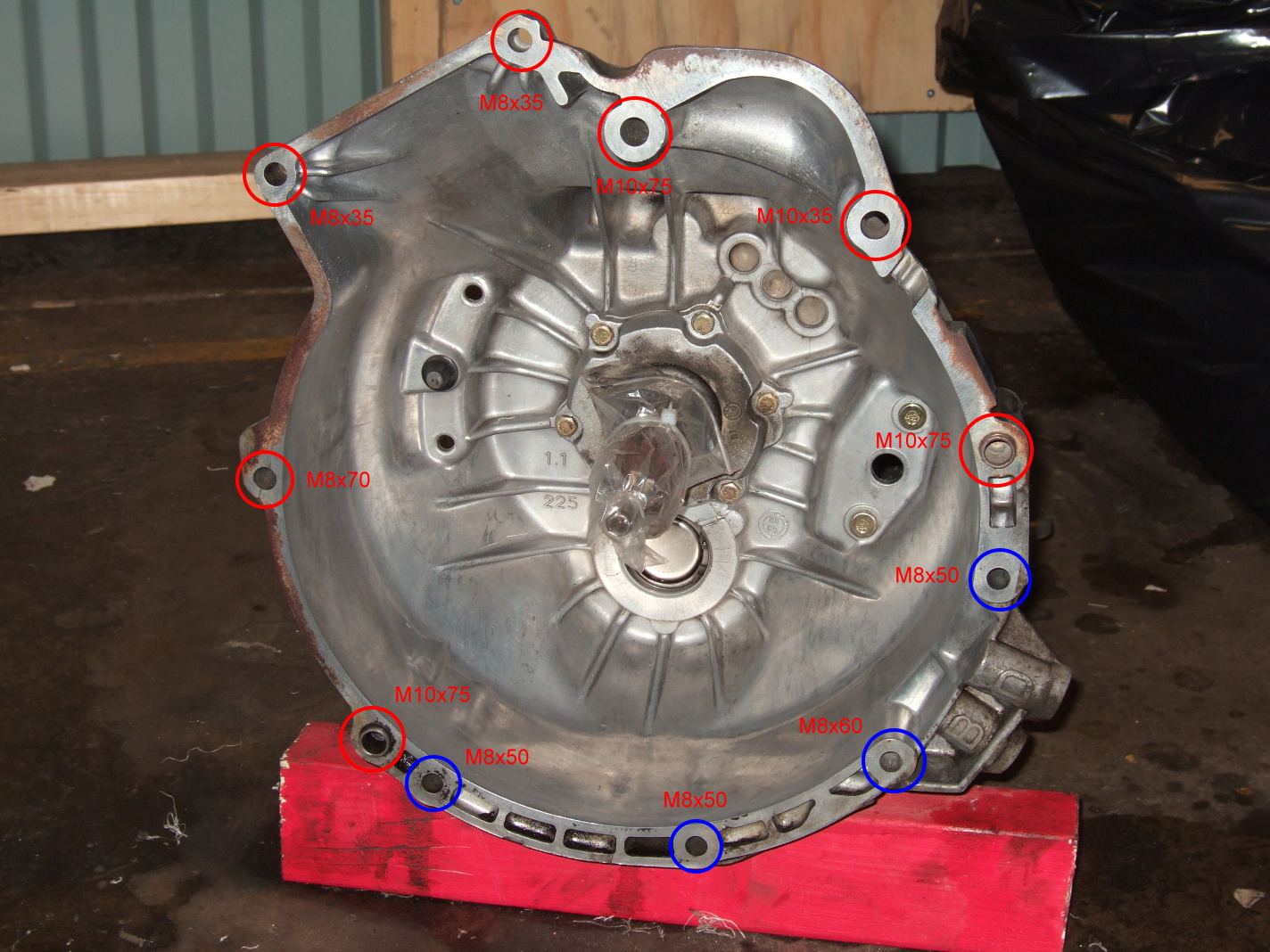 A schematic drawing of the location of all the gearbox and engine mounting Torx screws. All M8 bolts have a T10 head and all M10 bolts have a T12 head. The bolts marked in blue are mounted against the oil pan, the rest against the engine block. Some of the Torx screws are really hard to reach and work with.
But if you have the following tools I can guarantee this is everything
you need (but I can not guarantee success though). I list the tools
you need with some advice below.
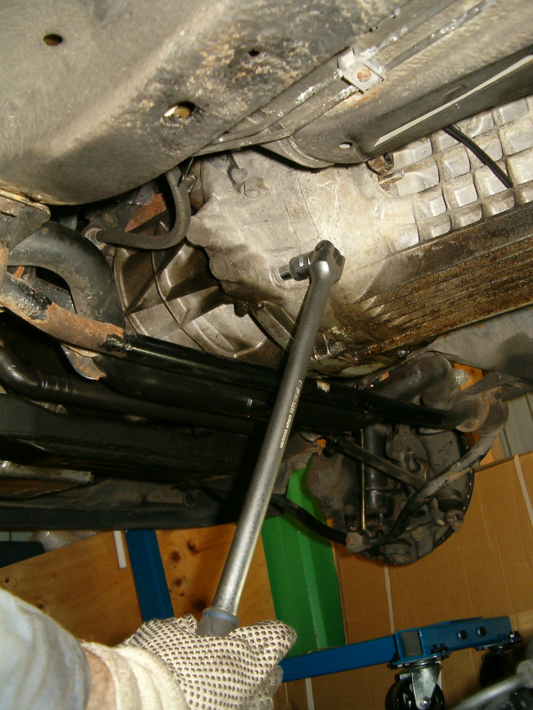 Removing one of the easy Torx screws using a good 1/2" socket and a long breaker bar. To the more accesible screws I can recommend a socket and your longest breaker bar. To the more inaccesible screws (basically the four at the top) I can recommend the following combinations (see the schematic picture above for the location).
The M10x35 bolt
    Start with
       - breaker bar
       - socket extension bar (400 mm)
       - socket (T12)
    Proceed with (after loosening)
       - ratchet handle (250 mm)
       - socket extension bar (400 mm)
       - socket (T12)

The M10x75 bolt
    Start with
       - breaker bar
       - socket extension bar (400 mm)
       - socket (T12)
    Proceed with (after loosening)
       - ratchet handle (250 mm)
       - socket extension bar (400 mm)
       - socket (T12)

The M8x35 bolts
    Start with
       - ratchet handle (250 mm)
       - socket extension bar (250 or 400 mm)
       - universal joint
       - socket (T10)
       and work from right side of the gearbox
 One tranny down! 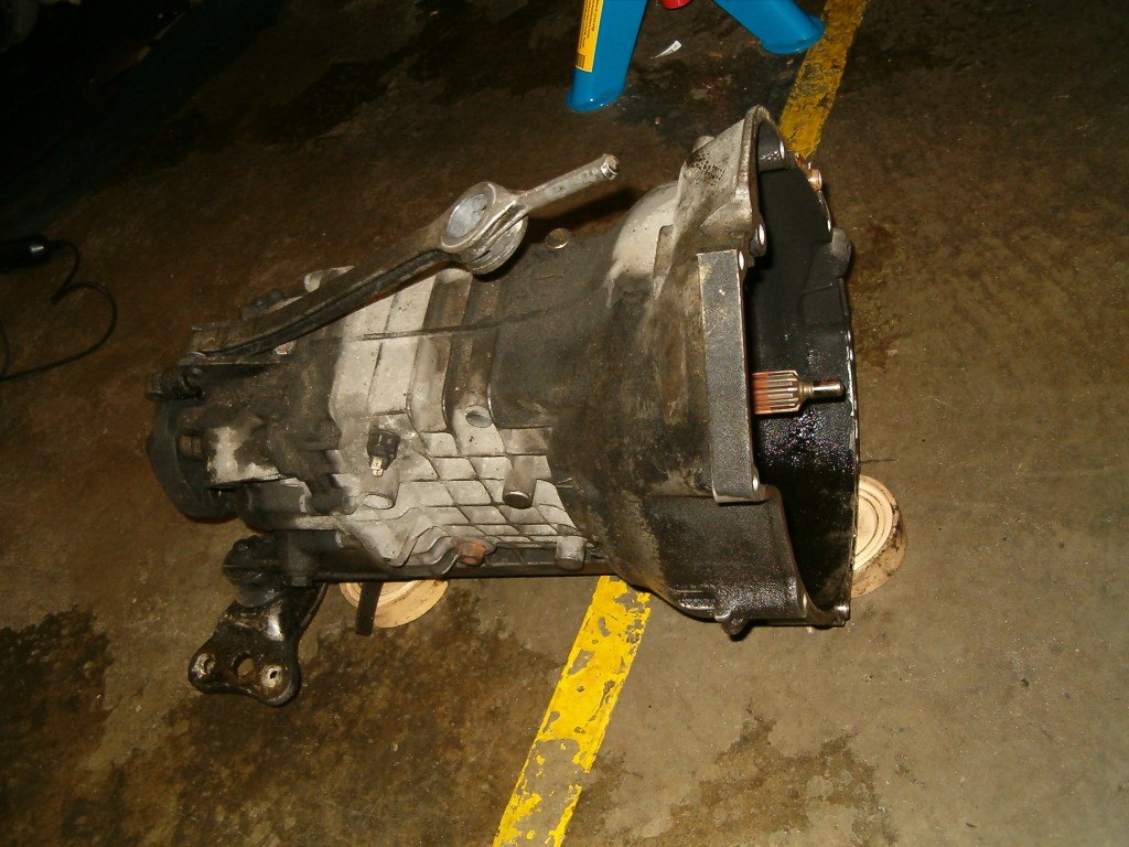 One tranny down! |