Overview
- Introduction
- Tool, Skills And Parts
- Preparing Block
- Painting Block
- Cleaning Block
- Installing Main Bearing Shells
- Installing Crankshaft
Introduction
In this part we assume the cylinder block have just arrived back from your favorite machine shop with all the machine work needed in order to start assembly the engine. It could be everything from a simple cylinder block resurface up to a full-blown true racing competition remachining. We will gradually install part by part until we end up with a complete engine.
Tools, Skills And Parts
The job is very straightforward and does not require any special tools.
Difficulty Level
![]()
The following tools are required for this particular work (tools marked with green checkmark are optional).
| small sledge hammer | ||
| drill | ||
| gasket removal disc | ||
| assembly lube (or oil) | ||
| torque wrench | ||
| ratchet | ||
| socket (17 mm) | ||
| socket (24 mm) | ||
| socket (32 mm) | ||
| tap (M6-1.00) | ||
| cutting oil | ||
The following spare parts are required for this particular work (parts marked with green checkmark are optional). Note that the BMW internal numbers are intended for a BMW 535i E34 -89.
| core plugs (45 mm) | 11 11 1 714 712 (6 pcs) | ? SEK | |
| core plugs (36 mm) | 11 11 1 717 939 (1 pcs) | ? SEK | |
| main bearing shells (red 60.00 mm) | 11 21 1 261 041 (12 pcs) | ? SEK | |
| main bearing shells with thrust washer (red 60.00 mm) | 11 21 1 261 033 (2 pcs) | ? SEK | |
| main bearing cap bolts | 07 11 9 912 680 (14 pcs) | ? SEK |
Preparing Block
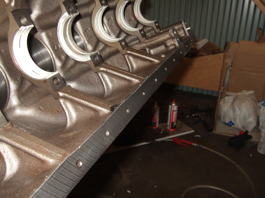
The cylinder block has just arrived from the machine shop. This specific block has been degreased, cleaned, milled and honed.

Picture 1 : A M30B35 block just after it has been cleaned, milled and honed.

Picture 2 : A M30B35 block just after it has been cleaned, milled and honed.
The cylinder block deck surface was milled 0.10 mm which is a normal procedure when rebuilding an engine to make sure you have good mating surfaces between block and head. And since this engine will have new piston rings the cylinders were honed as well. This is a must when installing new piston rings. If the cylinders are not honed there is a risk that the new piston rings does not brake in properly and you end up with piston ring leakage.
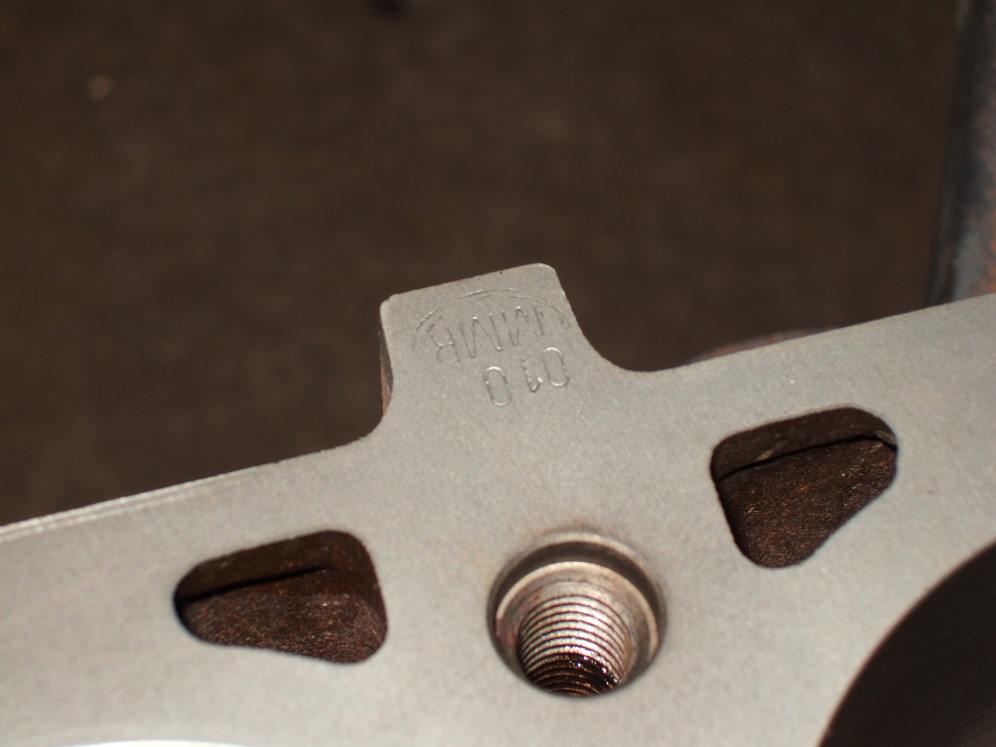
Picture 3 : The cylinder block deck surface was milled 0.10 mm (the cylinder head deck surface was also milled 0.10 mm).
Time to install the core plugs. But before you do that, take some 600 grit wet paper and some machine oil (or WD-40) and take a few turns on the mating surface between block and core plug and finish off cleaning with a rag to have a clean and dry surface free from any kind of rust or similar.
There are in total 7 core plugs on this specific type of cylinder block (M30B35). Six large ones and a smaller one. When installing a core plug, the trick is to knock it in square. For this I used an old 32 mm socket for the large core plugs and a 24 mm socket for the small core plug. Place the old socket in the core plug as seen in picture 4 and gently tap it with a small sledge hammer (or similar) in a 3-6-9-12 clock way. No sealing compound was used between the core plugs and the block.
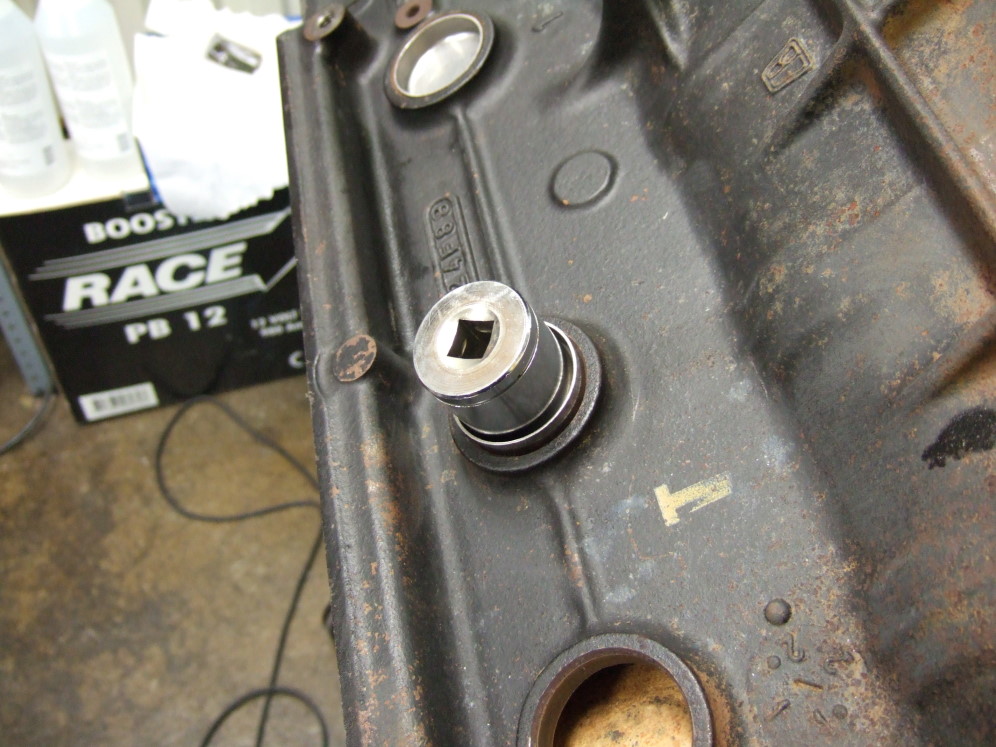
Picture 4 : Installing new core plugs with help of an old socket and a small sledge hammer for example.
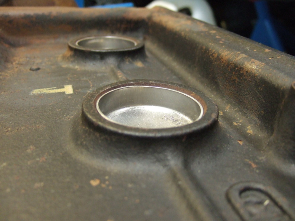
Picture 5 : New core plugs installed.
Painting Block
Next step is to paint the cylinder block in a nice colour. Not necessary but a nice touch on your engine rebuild project. I opted to use Corrostabil Engine Paint Black (which gives a glossy black colour) as I wanted to apply the paint with a paintbrush. In picture 6 you can see the result after two layers of paint and a couple of days drying.
A tip is to have a bottle of white spirit (lacknafta in Swedish) next to you when you paint in case you accidentely put some paint on the cylinder block deck surface or any other surfaces where you are not supposed to have paint.
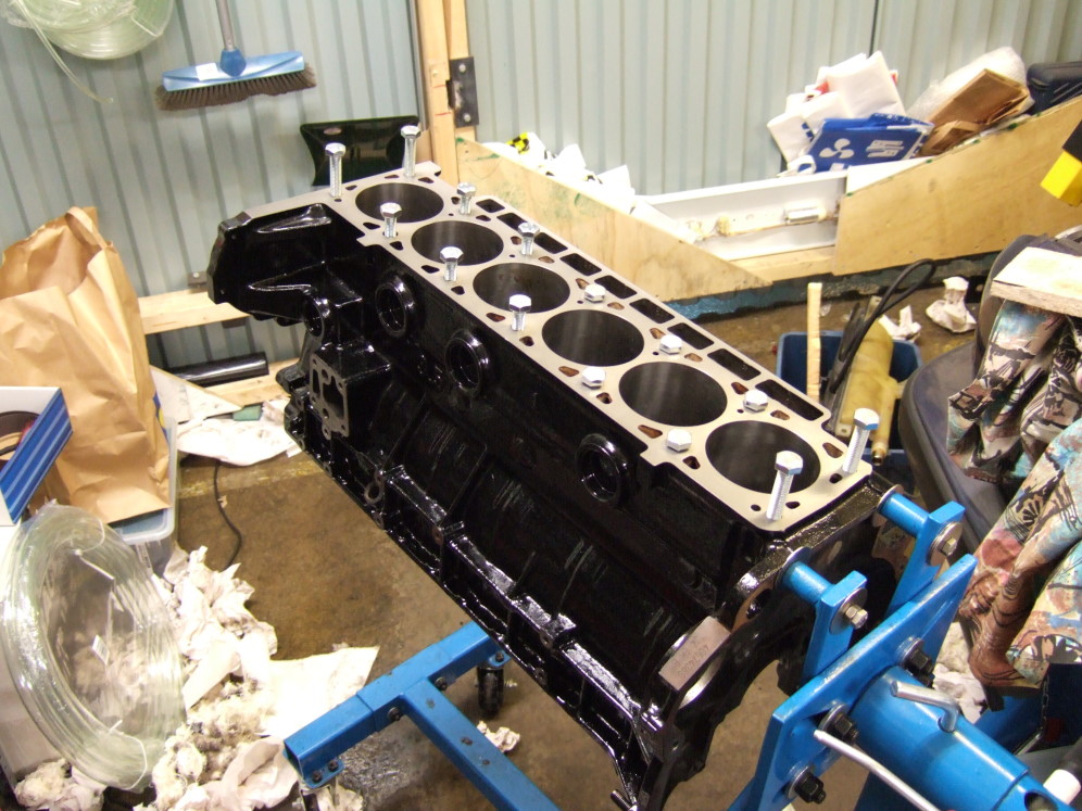
Picture 6 : The block painted in a nice glossy black engine paint.
Cleaning Block
Last step before starting to put together the engine is to do a thorough cleaning.
First we need to clean the oil sump bolt holes as some paint inevitably ended up here. I did not bother to mask or cover these holes as these holes should be cleaned with a thread tap anyway. So take a thread tap and use some cutting oil.

Picture 7 : The oil sump bolt holes cleaned with a thread tap and wrench.
Now it is a good time to clean surface against the the oil sump in order to secure a good surface for the gasket to avoid oil leakage. Remove, if any, paint using a rag and some white spirit. Then I really recommend to invest in some good gasket removal discs (use drill or even better a pneumatic tool). This will make your job easier and will result in perfect result (if used correctly). Be gentle and don't push the abrasive disc or in an angle against the surface.
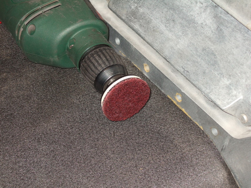
Picture 8 : A gasket removal disc mounted on a drill.
Now we turn our focus on one of the most important things to clean - the cylinder head bolt holes. The cylinder head bolts are some of the most important and critical but also most vulnerable bolts on the entire engine (conrod and crankshaft bearing cap bolts also falls into this category). If you skip this step and there is a lot of oil at the bottom of the hole there is a major risk you can crack your cylinder block wide open when torqueing the cylinder head bolts later on in your engine rebuilding project!
Each bolt hole is thoroughly cleaned. Start with adding some degreasing solvent into the hole and use a small bottle brush (I used a set of Mr Gasket engine cleaning brushes) to do the major cleaning. Put some cotton waste above the hole and stick a air blow gun into the hole and use the compressed air to remove the removed dirt and degreasing solvent. Repeat if necessary.
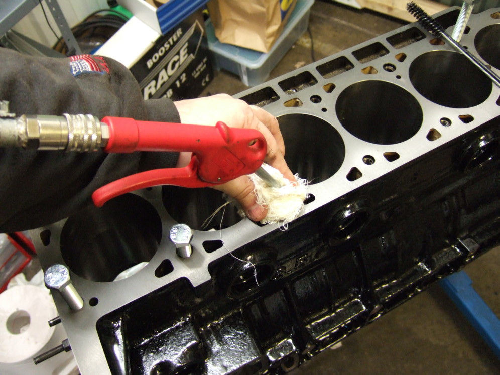
Picture 9 : Careful cleaning of the cylinder head bolt holes is a MUST!
Last step consisted of adding some WD-40 into each bolt hole and clean the threads using a clean bottle brush and finish of with compressed air into the bolt hole (with some cotton waist above it). And finally an ocular inspection was made in each hole using a falshlight to make sure a perfect result.
After this you should go through the entire cylinder block with compressed air to remove any trace of dirt, metal debries, dust or any kind of contamination. As a final touch each cylinder hole was covered with a thin coat of WD-40 to prevent any rust to build up.
Installing Main Bearing Shells
The block is now ready to receive the first parts which will be a new set of main bearing shells. It is recommended to replace the main bearing shells when rebuilding an engine. Especially on this specific engine which has been running for more than 360 000 kilometers. But as you can see in picture 10 the condition of the main bearing shells were surprisingly good for a 20-year old car with more than 360 000 kilometers on the odometer. That's exactly the shortest distance from the earth to the moon! So if you are looking for a reliable engine to use for your trip to the moon - choose an M30B35 engine :-)
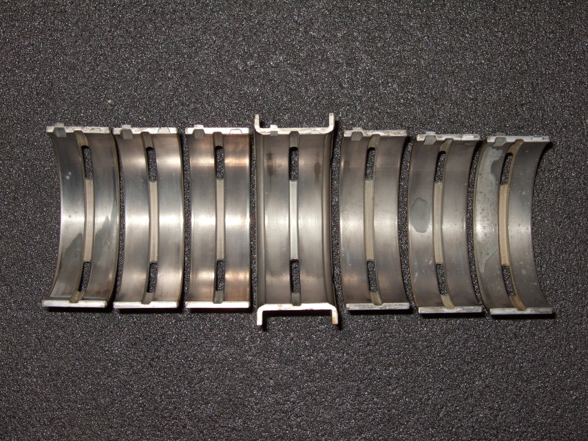
Picture 10 : The old main bearing shells from the block (not those in the caps).

Picture 11 : New main bearing shells (including two with thrust washers).
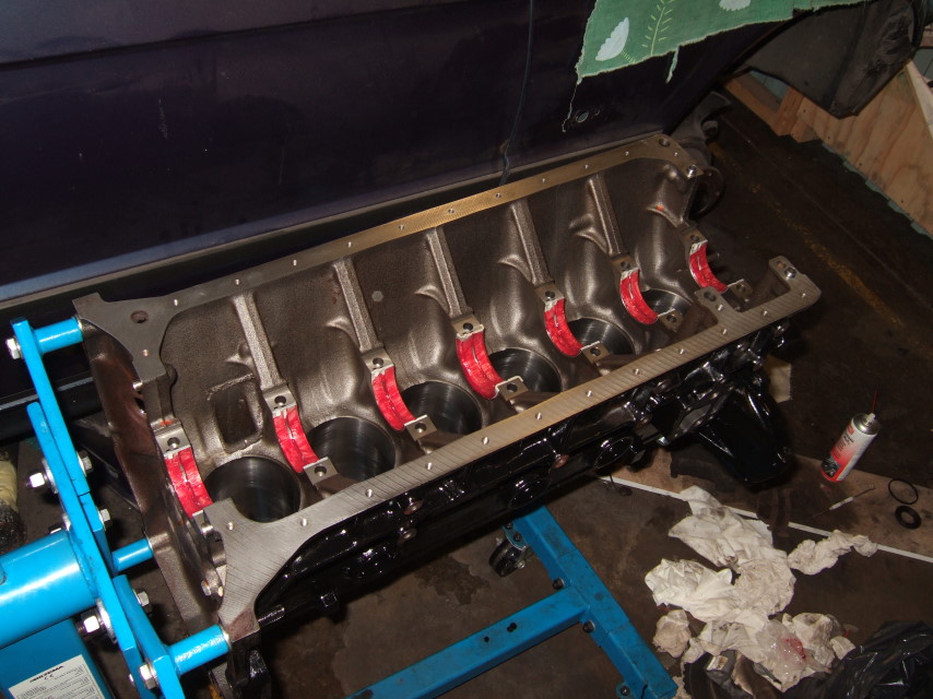
Start by installing the main bearing shells located in the block. The surface between the block and main bearing shell shall be absolutely dry and free from any kind of oil or grease. You should NOT lubricate between block and mainbearing shells!
The main bearing shells are easy to install. There are in total seven main bearing shells in the block (and then seven in the main bearing caps of course). The one in the middle is a little bit special as this one have thrust washers on each side to take up the axial forces from the crankshaft. So why not start with that one. Simply push into place and make sure the main bearing shell is flush with the surface on both sides, see pictures 12 to 15.

Picture 12 : Installing a main bearing shell (with a thrust washer) in the block.

Picture 13 : A main bearing shell (with a thrust washer) installed in the block. Notice the locking tab in the shell and the matching cutout in the block.
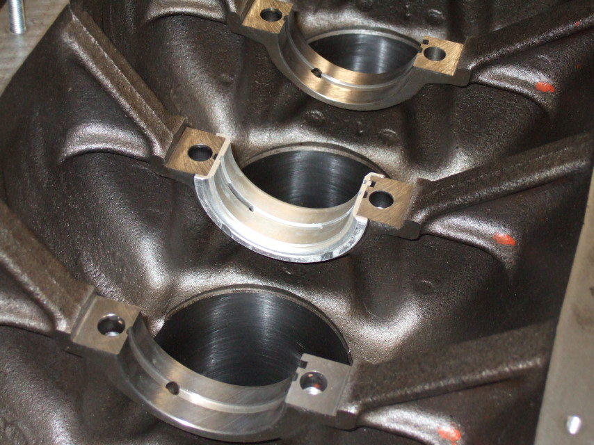
Picture 14 : A main bearing shell (with a thrust washer) installed in the block. Notice the locking tab in the shell and the matching cutout in the block.
Picture 15 : All main bearing shells installed (also visible is the cleaned oil sump gasket surface).
Installing Crankshaft
Before we install the crankshaft we shall prepare the main bearing caps. I took all my seven caps and put them into a degreasing solvent for a couple of hours. Then cleaned them with a nylon brush to get rid of all old oil sludge. You might want to apply a thin coat of WD-40 (wipe it on with a piece of rag or similar) if you don't know how long it will be before you have your engine ready.
Also always buy new main bearing cap bolts. These bolts have to withstand a considerable amount of punishment and you don't want one these to snap.
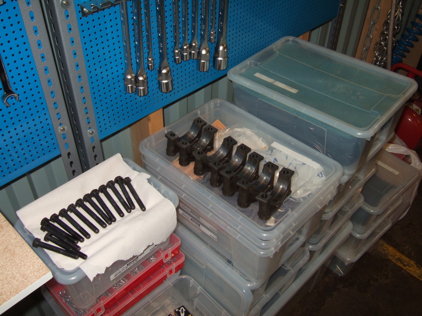
Picture 16 : Cleaned main bearing caps and bolts ready to be assembled.
Install the main bearing shells in the main bearing caps in the same way you did it in the block. Remember no lubrication between main bearing shell and main bearing cap, should be clean and dry.
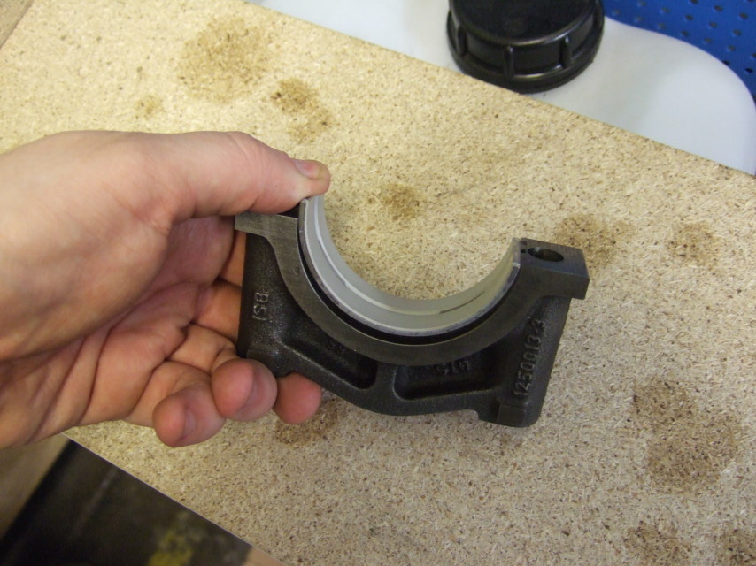
Picture 17 : Installing a new main bearing shell in a main bearing cap.
The final step before putting the crankshaft into the block is to lubricate the main bearing shells. If you plan to start up the engine within a short period of time after this you can use ordinary engine oil but in my case I opted for assembly lube (Red Line Assembly Lube) since I didn't know when the engine would be finished.
Put a thin layer on the main bearing shells - be careful not to put too much though, see picture 18.
The purpose of engine oil or assembly lube is of course to help lubrication during the cranking phase (when trying to start your engine for the first time) where you most probably will not have proper oil pressure and oil circulation.
Picture 18 : All main bearing shells coated with assembly lube (Red Line Assembly Lube).
Finally, everything ready to put the crankshaft into the engine! In the pictures below you can see the crankshaft (really heavy piece - you will be surprised) and all the main bearing caps with shells installed.
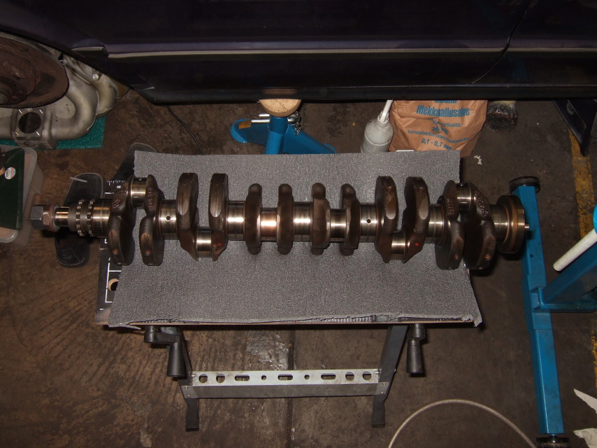
Picture 19 : The crankshaft ready to be assembled.

Picture 20 : All main bearing caps with installed main bearing shells ready to be assembled.
Grab the crankshaft at the ends and very carefully lower into place. Be very careful not to scratch it or even worse - drop it! Put some more assembly lube on the crankshaft journals and don't forget the contact surfaces for the thrust washers. Spin the crankshaft a turn or two just two make sure it rotates freely without any kind of resistance.
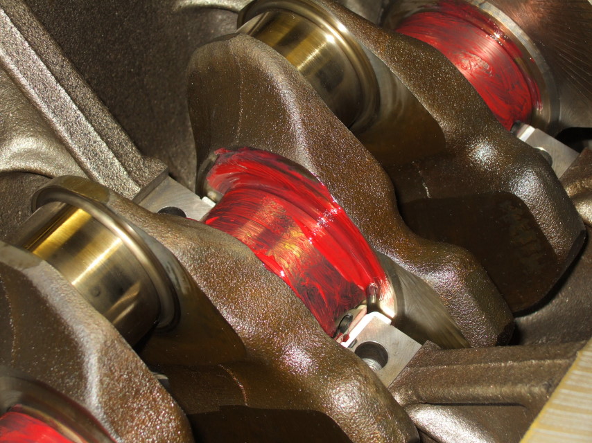
Picture 21 : Crankshaft journals coated with assembly lube (Red Line Assembly Lube). Notice the crankshaft contact surface against the thrust main bearing is also coated.
The main bearing caps are numbered (otherwise you are in big trouble if you didn't marked them when you took apart the engine) and it is extremely important that you install them where they belong. In this case they were numbered from 1 to 7 (1 to be at front of the engine or closest to piston 1).

Picture 22 : Each main bearing cap is unique and MUST be installed in the exact same location it was before.
Make sure you don't swap direction on the caps, the locking tab in the block and the locking tab in the cap should be on the same side, see picture 23.
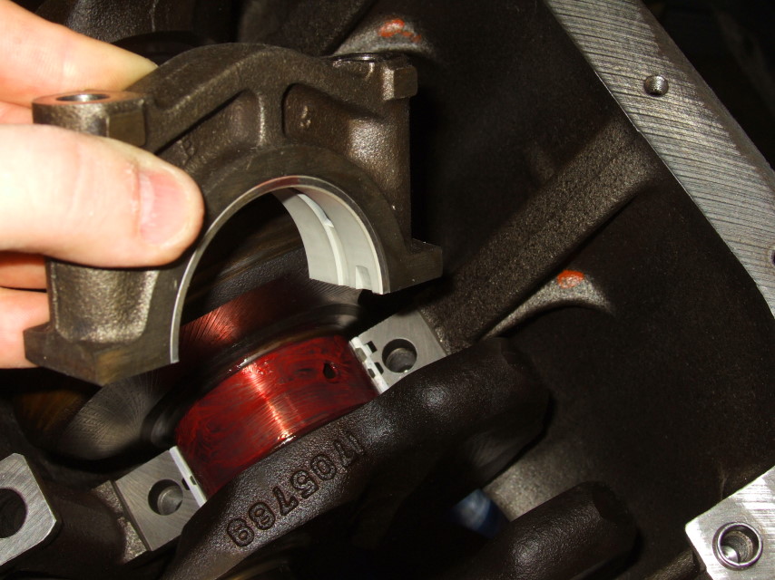
Picture 23 : Notice how the locking tabs on the two main bearing shells are on the same side.
Usually you must use a wooden block and a small sledge hammer or similar to knock the caps in place. You can hear on the sound when hammering when the caps are flush against the block (the sound will go from "hollow" to "solid" kind of). I put some duct tape around the wooden block to avoid any small pieces of wood falling into the block.
Picture 24 : Installing one of the main bearing caps.
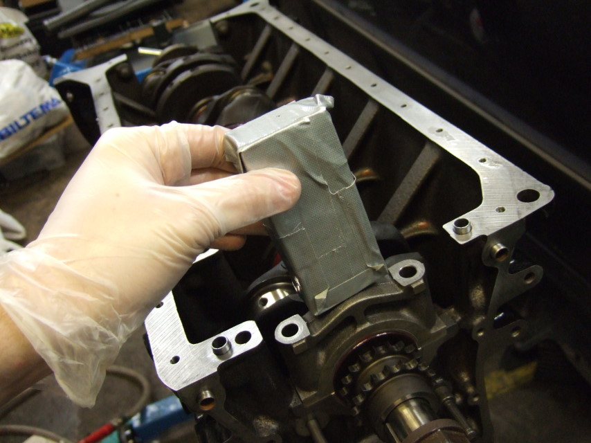
Picture 25 : Use a small sledge hammer and a wooden block or similar to drive the main bearing caps into place.
After knocking a main bearing cap in place, take two main bearing cap bolts and put some engine oil onto the threads and use a 17 mm socket and a ratchet and tighten the bolts just enough to keep the main bearing cap in place. After all main bearing caps installed torque them down to 60 Nm.

Picture 26 : All main bearings caps installed and torqued.
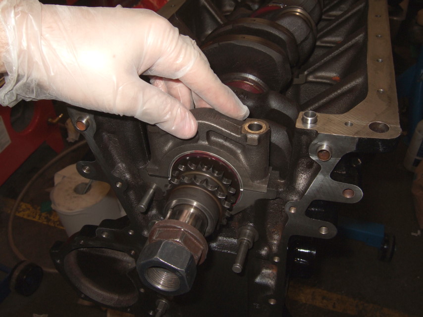
Last thing to do is to make sure the crankshaft rotate freely. Take a ratchet or similar and rotate the crankshaft. There shouldn't be any kind of resistance and especially not any kind of pinching somewhere when you rotate.
Picture 27 : Check the crankshaft rotates freely without any kind of resistance or pinching.