| |
||
Overview
The ProblemThe brake pads are a highly ordinary wear and tear spare part that needs to be replaced now and then. A good pratice is to look over the condition of the brake pads when for example changing tires in autumn and spring. Or if the warning light goes on, you should consider changing break pads in a quite near future. All E34 5-Series car are equipped with a brake pad wear warning system. However not all four wheels are equipped with a sensor, only one wheel per axle. For the front axle it is located on the left wheel and for the rear axle it is located on the right wheel. When a brake pad equipped with a sensor only has 3 mm of the brake lining left [2] a warning text will appear on the instrument panel (or a warning lamp will light up if your instrument panel is not equipped with text display). The recommended minimum thickness of brake pad lining (front and rear) is 2.0 mm [1]. However it is not recommended to wait until the warning light goes on since only one brake pad wear sensor is mounted for each axle. One sensor on the front left tire and one on the right rear tire. You can never know for sure the condition of the brake pad not equipped with a sensor, only guessing. There are a number of reasons why brake pads mounted on the same axle can wear unevenly. In this article the brake pads on the front axle will be replaced. But the procedure for the rear wheels is identical. Tools, Skills And PartsThe job is pretty straightforward and does not include any special tools. Difficulty Level
The following tools are required for this particular work (tools marked with green checkmark are optional).
The following spare parts are required for this particular work. Note that the BMW internal numbers are intended for a BMW 535i E34 -89. If you have any interest it is recommended to scan the aftermarket for brake pads that may suit you better than the original brake pads.
Removing WheelThe first step will be to remove the wheel at the location where you want to replace brake pads. This includes raising the car and later on also working beneath the car. Therefor a couple of rules are listed that must be followed:
Start by chocking the opposite end of the car from the end that is to be raised. If you only have the equipment to chock one wheel, choose the opposite diagonal wheel from the one you will remove. For example if you will raise the front left side of the car, you should chock the rear right wheel. 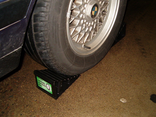 A wheel chocked using two plastic chocks placed on each side. Put your gearshift in 1st gear (or in Park if it is an automatic tranny) and then apply the parking brake (emergency brake). Don't skip to chock the rear wheels just because you have applied the parking brake. Remove the wheel hub cap, if any, with a small flat-blade screwdriver and loosen the wheel nuts. Remember, just loosen then, not unscrew them. Place the jack pad under a structure bearing part of the car (see owner's manual). Use a jack pad liner (for example wood or rubber) between the jack pad and the car to prevent damaging the car body. Raise the car to such a height you can place a jack stand next to the jack pad (with a jack pad lining between the jack stand and the car). Now lower the car with the jack until all weight is on the jack stand. As a precautionary move, leave the jack raised and let the jack pad have contact with the car body in order to be used as a very last emergency backup if the jack stand should fail. With the car raised, remove the wheel nuts and the wheel. The view in front of you should probably be quite like the one shown in the picture below. 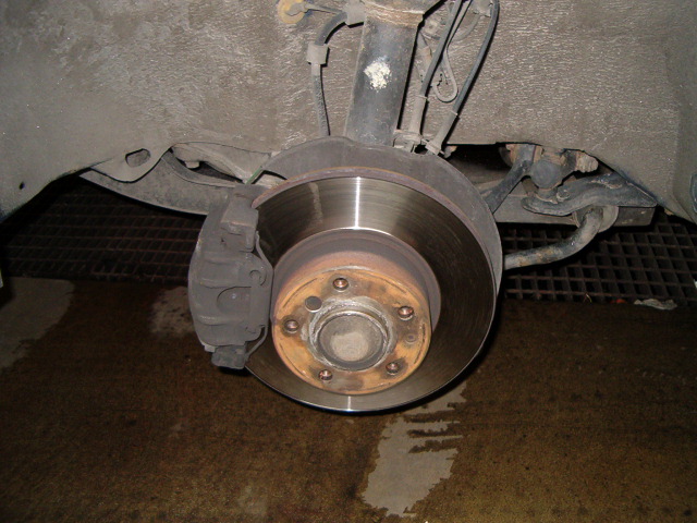 Left front wheel removed and the brake disc together with the brake caliper are visible. Removing Brake CaliperIf you are working on a wheel with brake pad wear sensor, start by disconnecting the sensor contact found directly behind the upper part of the brake disc. Simply pull it apart as seen in the pictures below. A brake pad wear sensor can be found at the front left and rear right wheel. 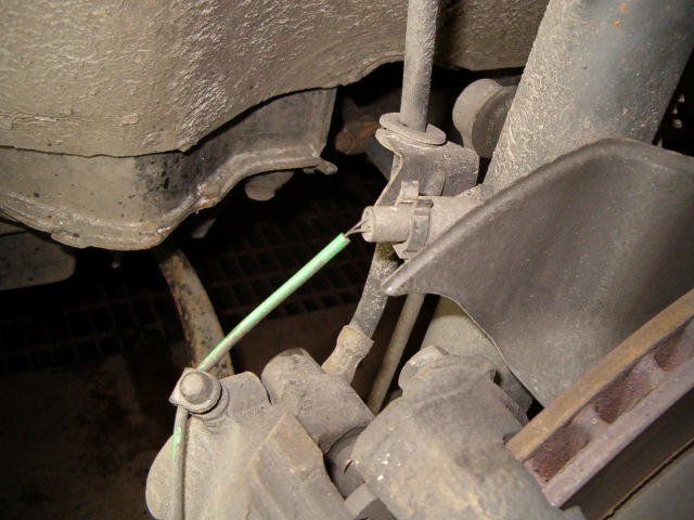 The location of the contact to the brake pad wear sensor behind the brake disc. 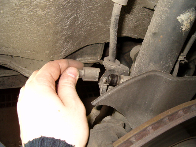 The brake pad wear sensor disconnected. Before the brake caliper can be removed the anti-rattle clip has to removed first. By using a small tire lever (or a large screwdriver or similar) and brace against the wheel hub, push the anti-rattle clip away from the wheel hub. The upper and lower "hooks" will come loose and the ant-rattle clip can be removed by hand. 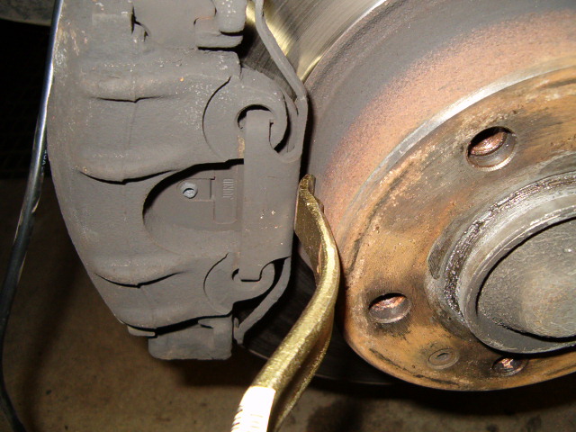 Place the tire lever between the anti-rattle clip and the wheel hub and push the clip away from the wheel hub. 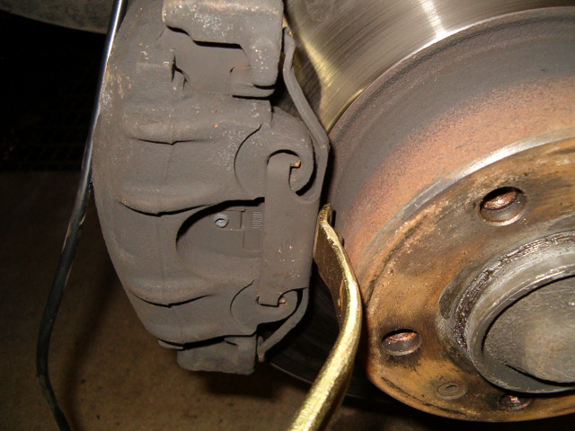 By pushing the clip away from the wheel hib the two "hooks" will be release and the clip can be removed. Use a small flat-blade screwdriver to pry off the dust caps covering the two guiding bolts. The dust caps are located on the backside of the brake caliper, see the picture below. To remove the dust caps, simply pry it loose and pull straigt out. 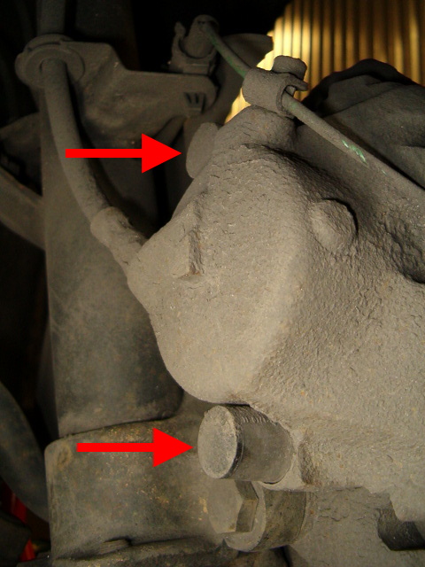
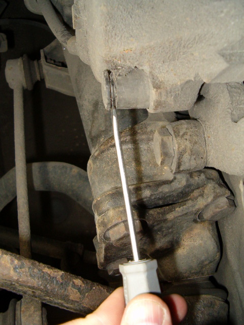 To the left the location of the dust caps for the two guiding bolts have been marked out with red arrows. To the right an example of how to remove the dust cap. Behind these dust caps the guiding bolts are located. Use a 7 mm Allen key to remove them. It is not necessary to remove the guiding bolts completely to remove the brake caliper but since you should always inspect and clean the bolts anyway you can remove them directly. Sometimes they can be hard to get loose but most of the times it shouldn't be any problem. Recommended is an Allen key socket mounted on a ratchet wrench (a short socket extension bar can also be handy to have). Please note that the 7 mm Allen key is a somewhat odd size and usually not included when buying an Allen key set. 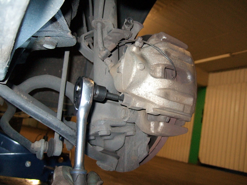 Removing the brake caliper guide bolts with a proper socket and ratchet wrench. After the guiding bolts have been removed the brake caliper is dismounted simply by pulling it straight out. Use a very small crowbar or large screwdriver if you find the brake caliper don't want to slide right off. Note! Never never let the brake caliper hang from the brake hose! Support it from the chassis with strong wire or similar. 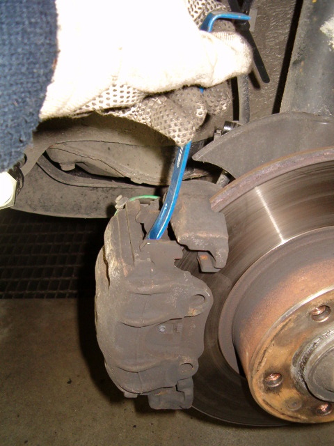 A very small crowbar or similar can be useful when loosening the brake caliper to be able to pull it right out away from the wheel hub. |
The inner brake pad will come out together with the brake caliper (and the outer brake pad will stay in the brake pad carrier). Remove the inner brake pad and support it with a stiff wire of bungee cord. Finally remove the outer brake pad from the brake pad carrier. 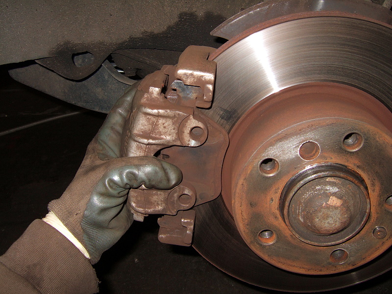 Pull the brake caliper straight out (the inner brake pad will follow and the outer brake pad will stay). 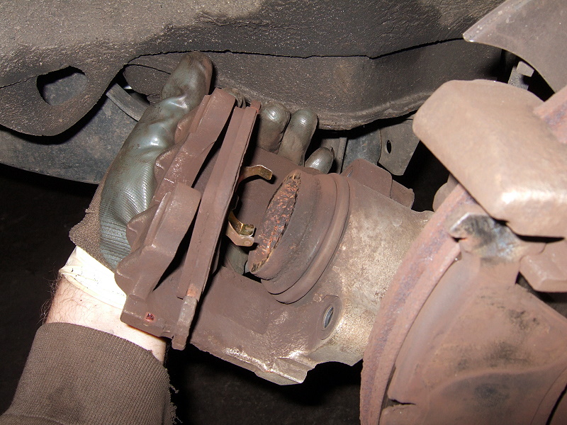 Remove the inner brake pad from the brake caliper. 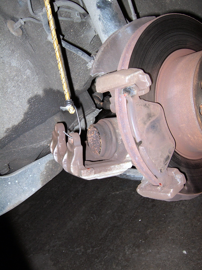 Support the brake caliper with a bungee cord or similar. Cleaning Brake DetailsStart by cleaning the guiding bolts. Wipe off grease and dirt and clean the threads using a brass brush. If necessary, use WD-40 and fine grit sandpaper (like P800 or similar) to remove any rust or hard-to-remove dirt on these guiding bolts. Also check for straightness (simply roll them over a plane surface and make sure they don't wobble). Note that the guiding bolts should not be lubricated when it is time to assemble the brake caliper. 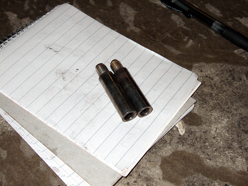 Guide bolts to be cleaned. Clean the brake caliper and the brake disc carrier with the steel brush. Remove as much dirt and dust as possible. Be careful not to damage the sensitive dust seal around the caliper piston mounted in the brake caliper. Take the opportunity to check the dust seal for cracks or damage. Any damage of this dust seal will quickly grow into larger problems such as seized pistons and similar. Avoid breathing the brake dust since brake friction materials may contain asbestos fibers. (Asbestos is nowadays forbidden in most countries but can be found on some older cars. Already in 1987 Sweden banned sales of new cars equipped with asbestos brakes.) Optionally clean the brake disc with CRC Bräkleen or similar to remove oil, grease and deposits. Inspecting Brake DetailsThis section is optional but recommended to perform at every (or every second) brake pad replacement job. Although the brake pads contains the softer material and thus are the wear component of the brake system, the brake discs will wear also. But they wear down in a much slower pace than the brake pads of course. Since the brake discs wear down, it is important to now and then make sure the thickness is above the recommended minimum thickness. Use a micrometer and measure the thickness of the brake disc (at the braking surface) at a set of different points and use the smallest measurement recorded. 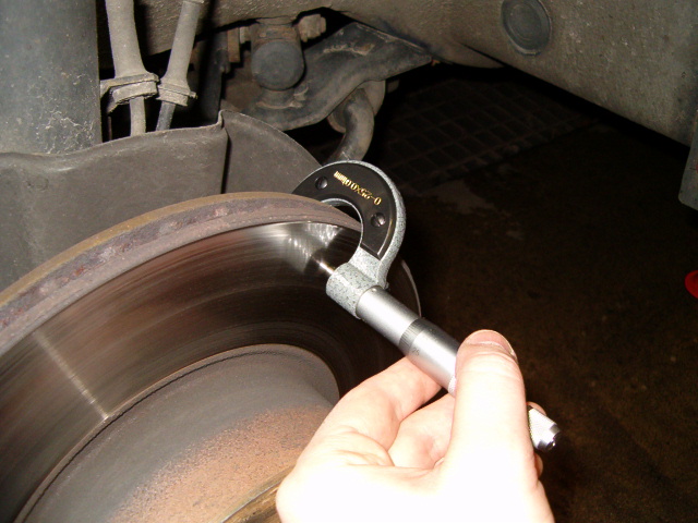 Measure the brake disc thickness with a microometer at eight to ten different points and use the smallest measurement recorded. Replacing Brake PadsSince the new brake disc and brake pads are a lot thicker you must push back the piston, otherwise you will never be able to slide the brake caliper back in place. You can use a brake pad spreader or a large polygrip (but be careful not to damage the dust seal around the piston if you use the polygrip). NOTE! Before you start pushing back the piston, take a look at the level of the brake fluid reservoir. If it's close to full you need to remove some using a syringe or similar. Because when you push back the piston the level of brake fluid will rise and eventually flow over (and brake fluid is very aggresive to paint so you really don't want to have brake fluid all over the place). 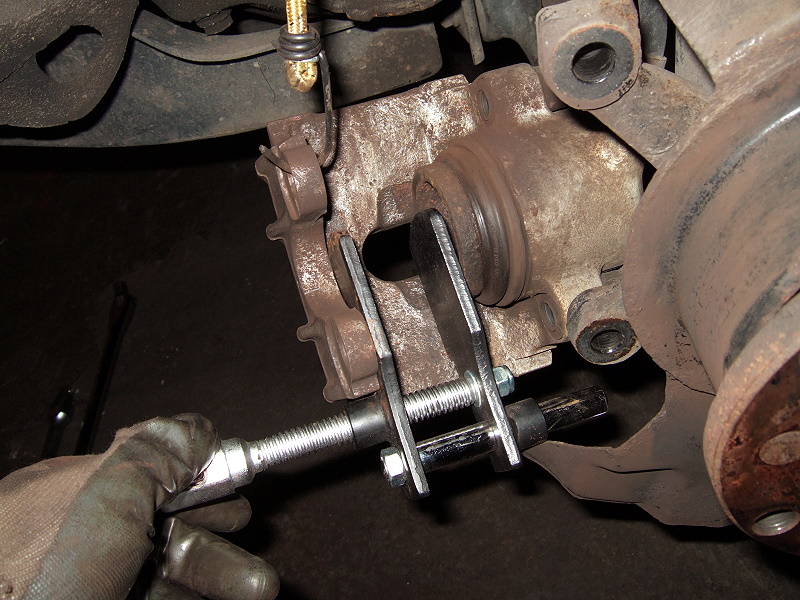 Press back the caliper piston into the brake caliper (to make room for the thicker brake pads) by using a disc brake pad spreader. If the wheel you are replacing brake pads on is equipped with a brake pad wear sensor, insert the new sensor into the cutout in the new brake pad as shown in the picture below. The brake pad with the metal spring on the back shall always have the brake pad wear sensor. 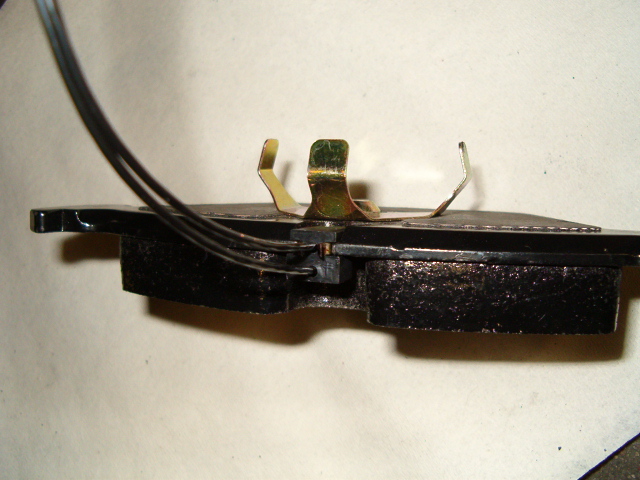 The brake pad wear sensor mounted into the brake pad (always mounted on the brake pad with the metal springs on the back i.e. the one closest to the caliper piston). Smear a small amount of Loctite 8009 (or similar anti-seize) at the contact areas between the brake pads and the brake pad carrier to ensure smoother movement of these components. Do not apply any anti-seize on the brake disc surface or brake pad lining! If it should happen just remove it directly with CRC Bräkleen or similar. Place the outer brake pad in the brake pad carrier and the inner brake pad in the brake caliper with the metal springs into the hole of the caliper piston, see picture below. Route the brake pad wear sensor contact through the hole of the brake caliper and carefully slide the brake caliper in place on the brake pad carrier (as you did when you removed the brake caliper but in reverse).  Place the outer brake pad in the brake pad carrier (flush to the brake disc)... 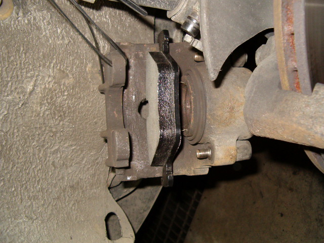 And then place the inner brake pad (with the metal springs into the hole of the caliper piston) into the brake caliper. Put back the guide bolts and tighten them down to 35 Nm. Put the dust caps back on. Reconnect the brake pad wear sensor. It is highly recommended to guide the wire for the sensor through the dust cap of the bleeder bolt, otherwise it is very likely the rim will scuff against the wire and after a while the wire is cut off. Finally put back the anti-rattle clip. 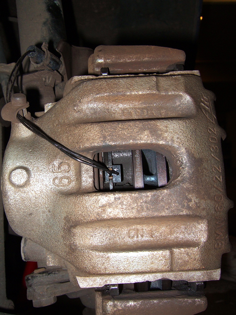 Correctly located brake pad wear sensor wire. Put the wheel back on and do the wheel bolts hand tight, remove the jack stand and slowly lower the car until the wheel slightly touches the ground (enough to keep it still while you tighten the wheel bols). Tighten the wheel bolts their final torque, usally around 100 Nm. Lower the car completely and remove the wheel chocks. NOTE! Depress the brake pedal several times BEFORE you use your car, this to ensure the piston and brake pads are located correctly - which is tightly against the brake disc. Tightening Torques
Thickness SpecificationsThe minimum thickness specifications for front and rear brake discs are listed below. The source for all values are BMW TIS [2]. If any hesitations what is valid for your car, the minimum allowable thickness is stamped on the wheel hub for all original equipment brake discs.
|