| |
||
Overview
The ProblemThere are several symptoms where you can suspect bad dampers or springs or both. In my case the first obvious sign was that the front left damper had started to leak oil. Shortly after that other symptoms appeared such as bad ride quality and bad handling over joints and bumps in the road. One other distinct symptom was when driving in a left-hand bend and let the left wheel hit a manhole (lowered a bit into the road) which caused the left wheel (with the totally broken damper) to bounce furiously. Tools, Skills And PartsThe job is in the middle of the scale and requires only a couple of special tools. Usually you encounter at least one unforeseen problem so reserve a full day to be on the safe side. Difficulty Level
The following tools are required for this particular work (tools marked with green checkmark are optional).
The following spare parts are required for this particular work (parts marked with green checkmark are optional). Note that the BMW internal numbers are intended for a BMW 535i E34 -89.
Please note that the E34 series changed damper construction at several occasions (inclusive the 535i model) and you need to be extra careful when buying spare parts. There were three different models for the E34 series depending on the manufacturing date.
      - up to 07/90   M12 (short 41 mm piston round cap)
07/90 - up to 09/92   M14 (long 44 mm piston round cap)
09/92 -               M14 (new design four spoke cap)
Removing The Spring StrutAs this job does require minimum under-the-car work it may be tempting to not use any jack stands. But never never work under a car not supported by one or more jack stands! I would also like to point out that springs and dampers shall be replaced in pair i.e. if you replace the left side spring you shall also replace the right side. Step 1 : Removing The Wheel Start by loosen the wheel bolts (justloosen them slightly). Chock the rear end wheels with wheel chocks to prevent the car moving when you raise it with a floor jack. If you only have two wheel chocks, choose the opposite diagonal wheel from the one you will remove. For example if you will raise the front left side of the car, you should chock the rear right wheel. 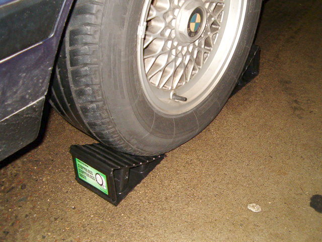 A wheel chocked using two wheel chocks placed on each side. Place the floor jack (strongly recommended to use a jack pad liner such as wood or rubber between the
floor jack and the car) under a structure bearing part, raise the car and place a jack stand. This job
does not require the car to be raised to any high levels.
Step 2 : Removing The Brake Parts Remove the brake fluid hose from the support located on the spring strut.  The brake fluid hose removed from the support on the spring strut. Disconnect the brake pad wear sensor cable contact and remove it from the support located on the spring strut (only applicable for front left wheel). 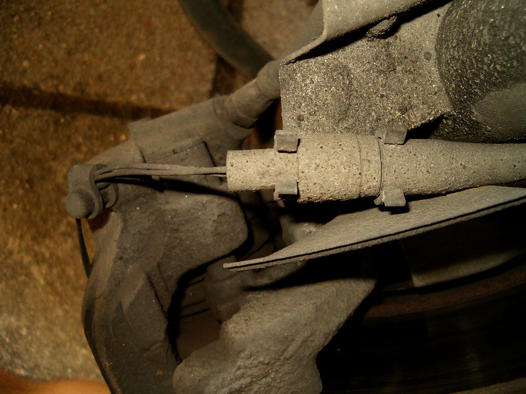 The brake pad wear sensor cable contact to be disconnected.  The location of the brake pad wear sensor cable support on the spring strut (see red arrow). Remove the ABS sensor cable from the supports located on the spring strut (two locations). 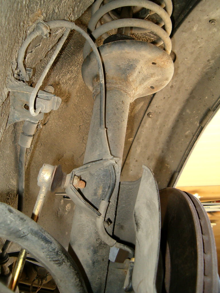 The location of the ABS sensor cable supports on the spring strut (see red arrows). Remove the ABS pulse sensor located behind the brake shield. Use a 5 mm Allen key socket (1/4") and a ratchet handle (1/4") to remove the screw. Then carefully twist and turn the ABS sensor to remove it from the hole of the spring strut.  The location of the ABS sensor behind the brake shield. Time to remove the brake caliper and brake pad carrier. This can be removed as one
single unit (the brake caliper is mounted on the brake pad carrier with two 7 mm Allen
guiding bolts).
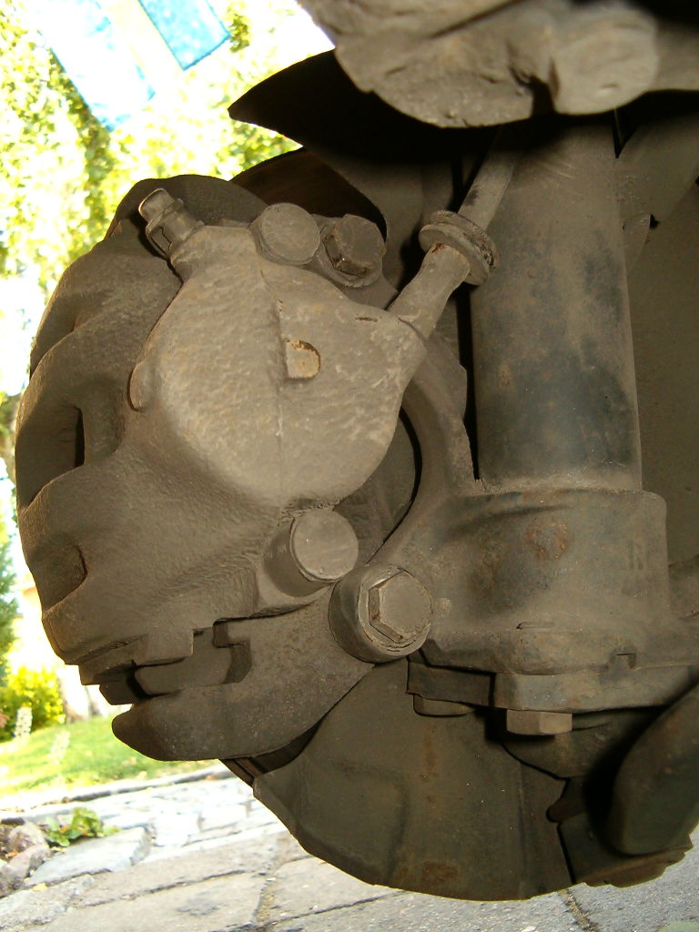 Location of the two 19 mm hex head screws holding the brake pad carrier to the spring strut. Use a 19 mm 6-point (1/2") socket and a long breaker bar (1/2") to remove the two screws holding the brake pad carrier to the spring strut. 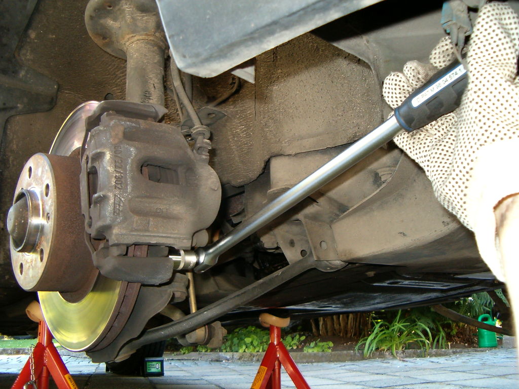 Use a 19 mm 6-point 1/2" socket and a long 1/2" breaker bar to remove the two 19 mm hex head screws. Now simply slide right off the brake caliper + brake pad carrier from the brake
disc. Use a very small crowbar or large screwdriver if you find it doesn't want to slide
right off.
As a final step remove the brake disc. It is now attached to the wheel hub only with a single 5 mm Allen screw. Use a 5 mm Allen socket (1/4") and a ratchet handle (1/4") to remove it.  Use a 5 mm Allen socket (1/4") and a ratchet handle (1/4") to remove the screw holding the brake disc to the wheel hub. Step 3 : Removing The Suspension Parts Disconnect the stabilizer link from the spring strut. It is attached to the spring strut with a 16 mm hex head nut. 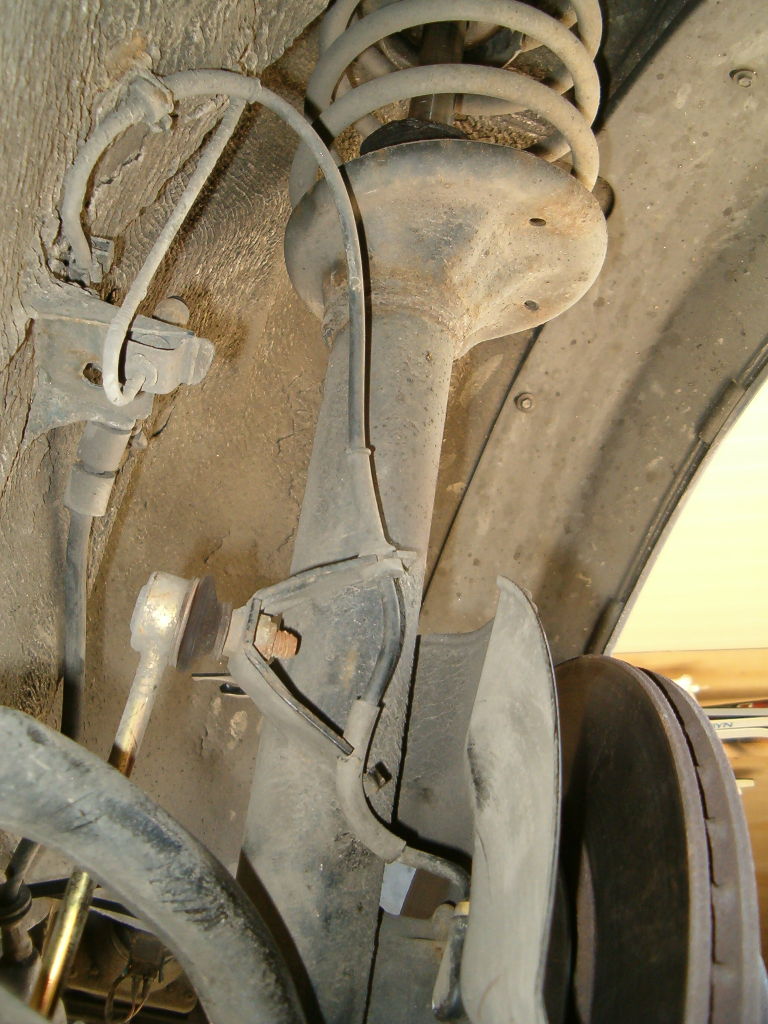 The stabilizer link attached to the spring strut with a 16 mm hex head nut (see red arrow). However you need a counterhold to remove the nut otherwise it will just spin around in the ball joint of the stabilizer link. There is already a suitable location to apply a counterhold on the stabilizer link - a 16 mm grip between the rubber boot and the support. Just be very careful not to damage the rubber boot of the stabilizer link. 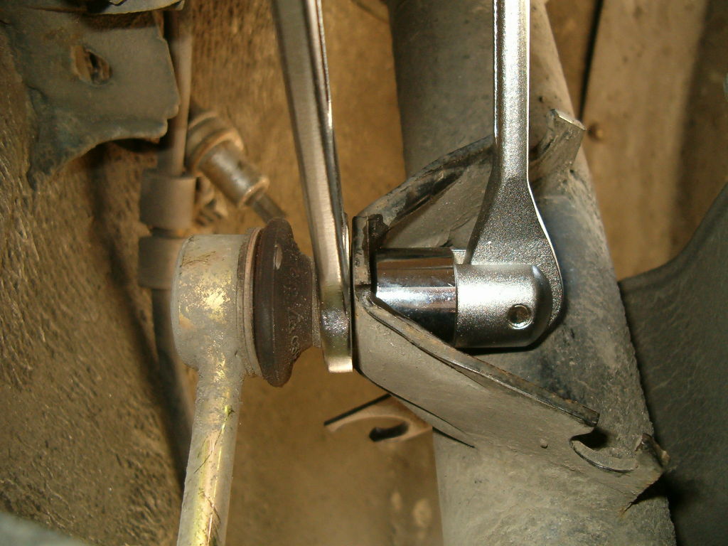 Use a 16 mm open-end wrench as a counterhold and a 16 mm swivel joint wrench to unscrew the nut. Next step is to separate the spring strut and the steering arm. These are held together by three 19 mm hex head screws (see picture below). Use a 19 mm 6-point 1/2" socket and a long 1/2" breaker bar to remove them. The two parts will most probably not separate immediately after you have removed the three screws - this is quite normal. Simply leave at it is and proceed - they will separate anyway in the next step. 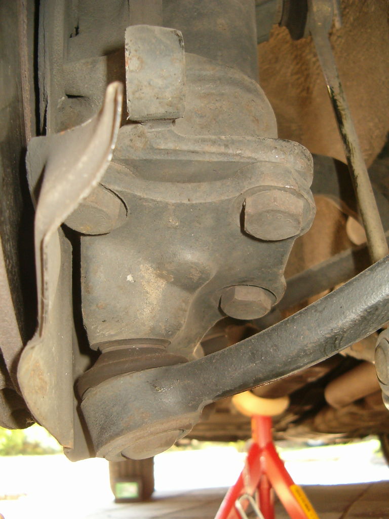 The spring strut and steering arm mounted together with three 19 mm hex head screws (see red arrows). And now to the very last step before you have your spring strut completely free. At this point there is only the three screws in the strut tower holding the spring strut. So before you start undo those screws - make sure you have a helping hand holding your spring strut. Otherwise you will most probably experience how suddenly the heacy spring strut is coming loose and drop directly on your toes!  The dust cap and the three 13 mm hex head screws (see red arrows) on the strut tower. Start by remove the dust cap covering the top of strut and damper assembly. Then remove the three 13 mm hex head screws holding the entire strut assembly attached to the strut tower. Use a 13 mm socket and a ratchet to remove the screws. Then simply remove the complete spring strut.  One piece of front strut assembly complete with damper and spring. Disassembling The Spring StrutStart by decompressing the spring using at least three spring compressors. I noticed that only two was not enough - they where simply not long enough to compress the spring to such a level needed for this job. |
I had to start with two and compress as much as possible - then I hooked on two new and compressed the last bit. It is even more crucial in the assembly step to be able to compress the spring to such an extent that all pieces can be correctly mounted. 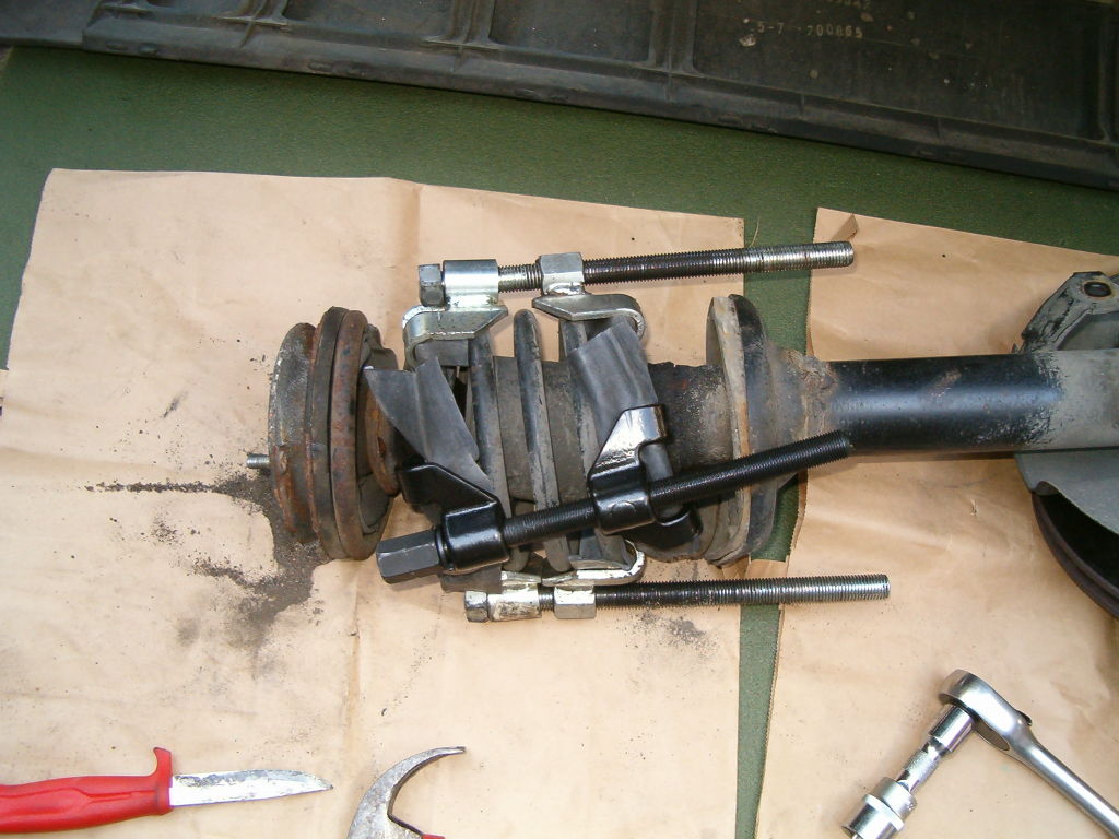 Compress the spring with at least three spring compressors or use a professional spring compressor. Compress the spring until the tension is fully released between the spring and the strut mount. Now remove the damper top nut by using a 19 mm offset box-end wrench and a 6 mm Allen socket (1/2") together with a ratchet handle (1/2"). Note that old top nuts from BMW are 19 mm while the new ones are 18 mm. The top nut included in the Sachs package was also 18 mm. 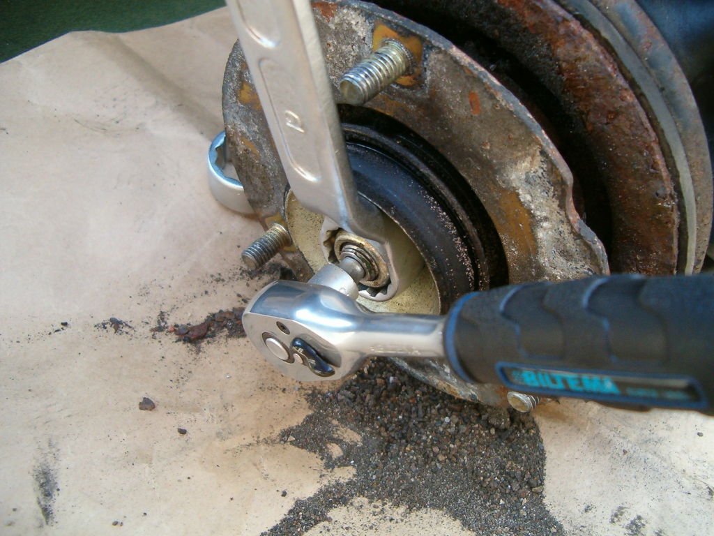 Remove the damper top nut using 19 mm offset box-end wrench and a 6 mm Allen socket (1/2") together with a ratchet handle (1/2"). Now you can dismount damper top nut, stopper, strut mount, upper spring pad, spring, support, spacer, bump stop, protection tube and finally lower spring pad. See the picture below for all the pieces laid out in the correct order as they were dismounted.  The front strut assembly completely disassembled into pieces. From left to right we have : damper top nut, stopper, strut mount, upper spring pad, support+spacer, bump stop, protection tube and lower spring pad. 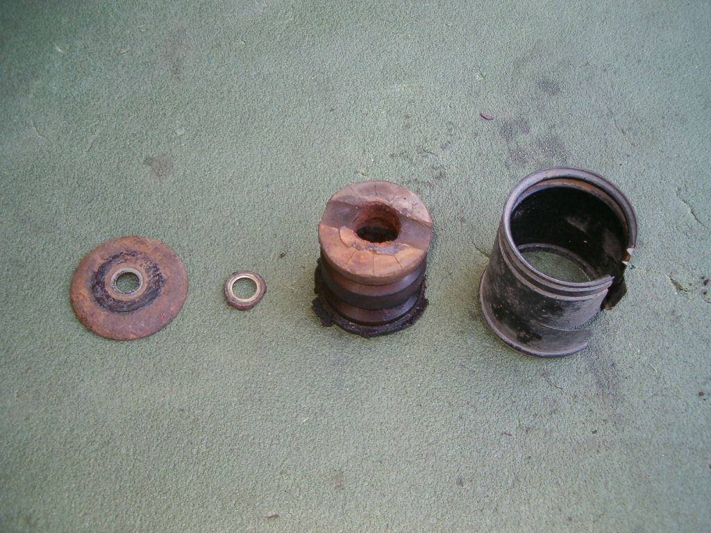 From left to right we have : support, spacer, bump stop and protection tube. 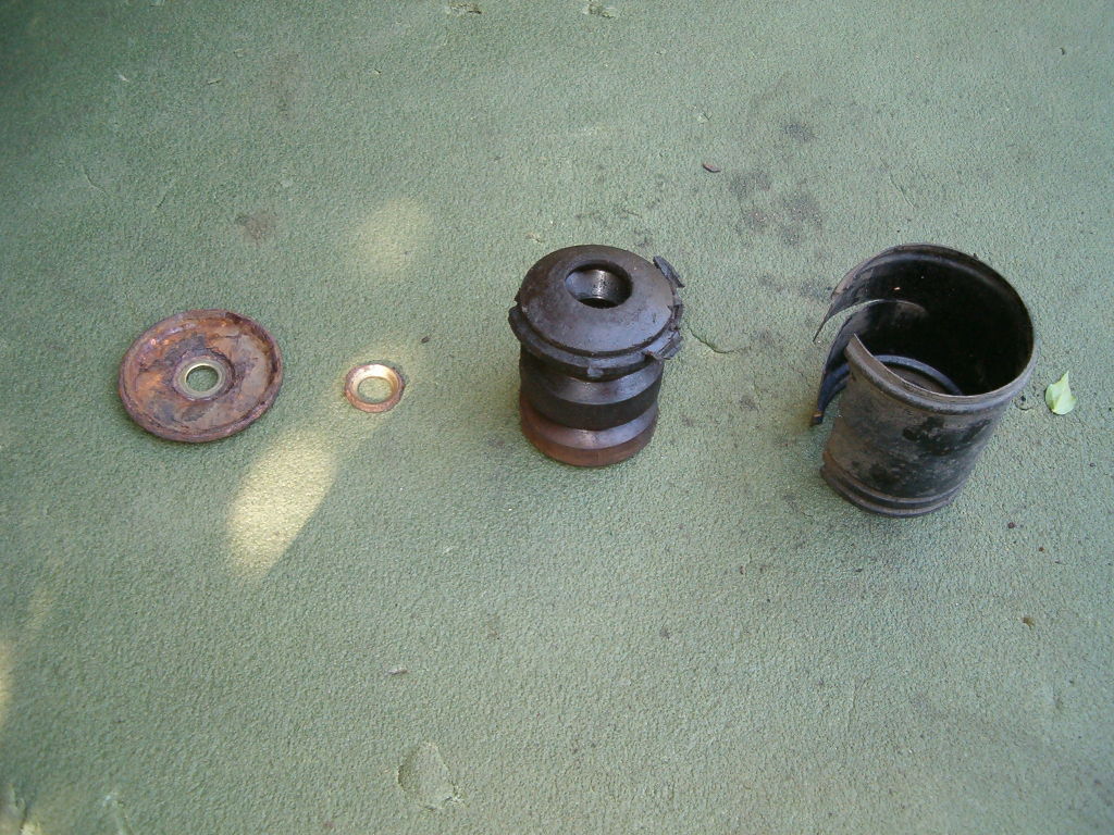 From left to right we have : support, spacer, bump stop and protection tube. Time to remove the damper. It is mounted and held in place by a large threaded ring on the top of the spring strut. Put the spring strut into a solid vise. Take your largest plumber wrench and extend it with 1 meter long metal pipe or similar (you will need it) and try to remove the threaded ring (collar nut). If you are going to reuse the damper be very careful not to scratch the piston. 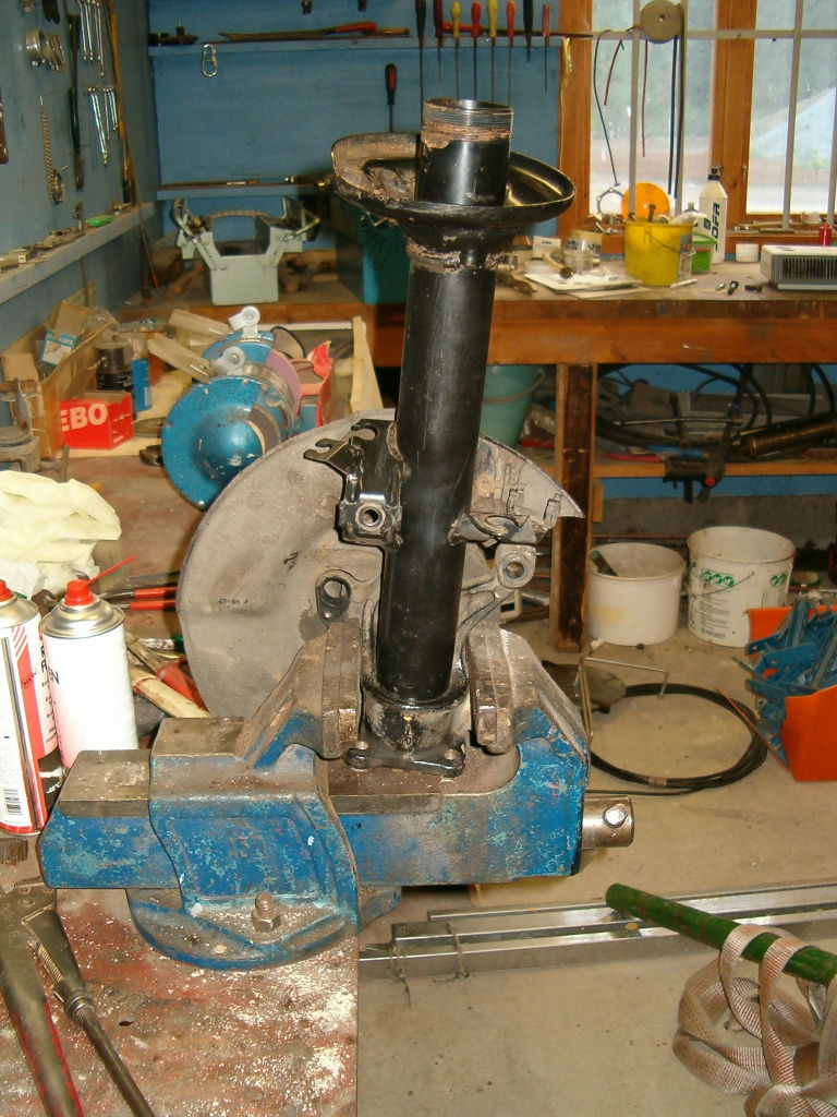 The spring strut mounted into a very solid and stable vise for removal of threaded ring (has already been removed).
After you have managed to remove the threaded ring you can now simply remove the damper by pulling it straight up. Remove any oil left in the spring strut by turning it upside and let it stay there for a while or so. 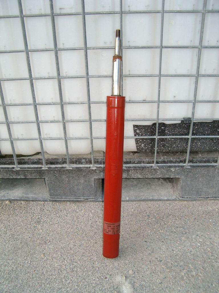 The old broken damper - original BMW (31 32 1 135 675). Assembling The Spring StrutAfter all old oil has been removed from the spring strut, pour approximately 10 cl of any ordinary engine oil into the spring strut and carefully lower your new damper. Be always very very careful about the piston of your new damper. Not all agree with the idea to pour oil into the spring strut. The idea behind it is to improve heat transfer (to cool down the damper) and/or to prevent the components from start rusting. If none of these two turned out to be true you will never harm any components or reduce the performance by pouring oil into the strut spring. So with two (possible) positive effects and none negative effective, I recommend to pour oil. Clean the threads on the spring strut thoroughly and carefully mount your new threaded ring and tighten it with the very same pipe wrench you used before. If suitable, mount the the small ring (spacer) and top nut as well, then you know where they are anyway. 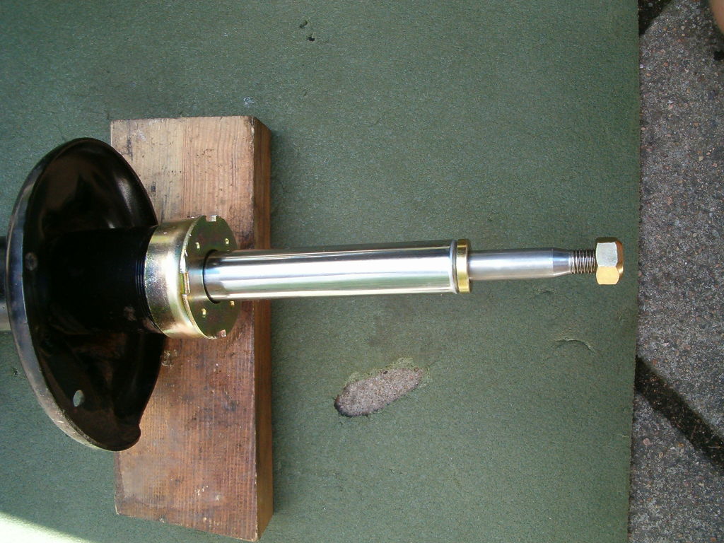 The new damper installed with new threaded ring, spacer and top nut. While you have everything disassembled it's a good opportunity to clean the spring struts. One place in particulary you should clean is the big bowl at the top of the spring strut where the spring normally is attached. This is a place where a lot of dirts are collected and dirt holds moisture causing corrosion. If time allows paint with Hammerite Hammarlack at places where corrosion already started. 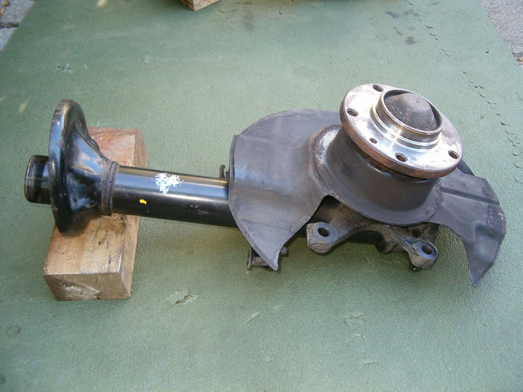 Halfway through with the cleaning job of the spring struts. 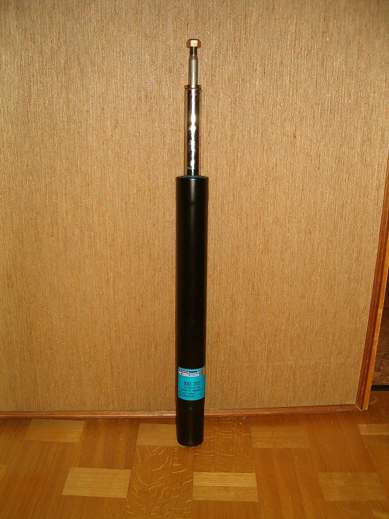
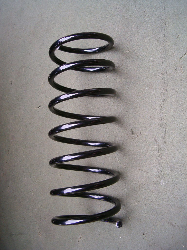 New Sachs Super Touring dampers and new Kilen springs. It's now time for the fun part when all your new parts shall be assembled together. But first let's take a quick look at an exploded view of the spring strut assembly. This view will give a clear picture of how all pieces are assembled together and all parts are marked with number with their corresponding names (as used in this guide) gelow.
 Exploded view of the spring strut assembly. Start by compressing the spring. You need to compress it quite a bit. Place the lower spring pad at the bottom of the spring strut and place the spring directly on top of it. Make sure the lower spring pad is correctly placed on the spring strut and also make sure the edges between the lower spring pad and the spring are flush against each other. 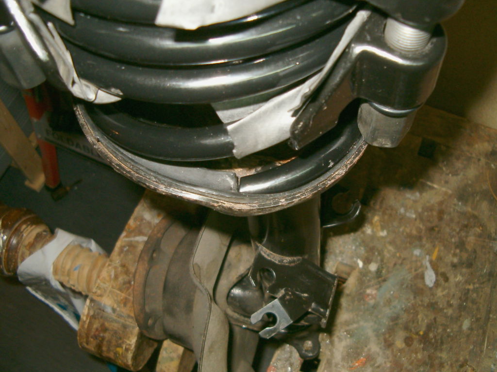 Make sure the edges of the lower spring pad and the spring are flush against each other. Put together the bump stop and the protection tube as seen in the picture. Now slip the onto the damper. If you encounter some resistance from the bump stop, remove the spacer and also lubricate the inside walls at the top of the bump stop with some ATF oil. Put back the spacer and support. You should have pushed down the bump stop just deep enough so the support rests on the spacer (no deeper). 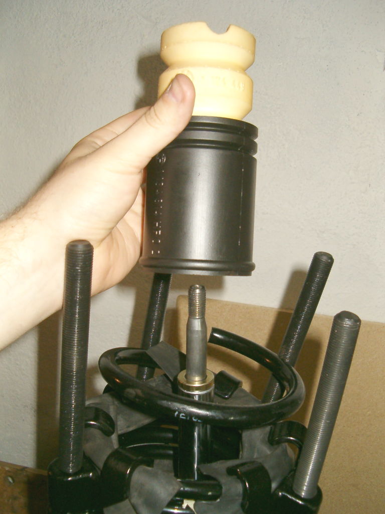 Slip the bump stop and protection tube onto the damper. 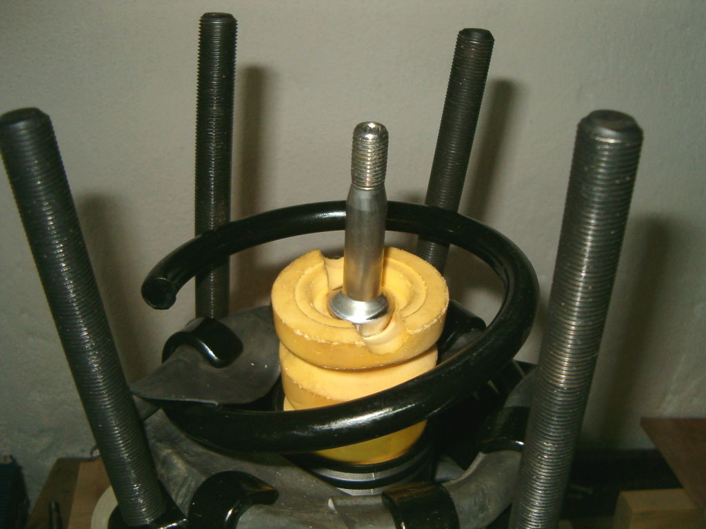 The bump stop and protection placed into correct depth. 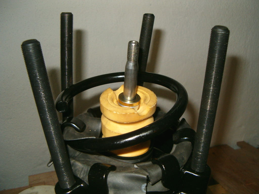 The spacer added. 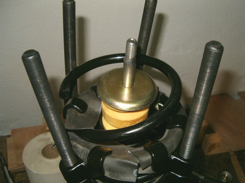 The support added (must rest on the spacer - not on the bump stop). Place the upper spring pad, then the strut mount and finally the stopper. Make sure the edges of the spring, the upper spring pad and the strut mount are flush against each other. Note! You must make sure that the strut mount is resting against the support (which in turn must rest on the spacer) and is not resting on the spring. When you place the strut mount onto the support you shall have a small gap between the spring and the strut mount - see the picture below. After you have verified this you can mount the self-locking top nut and tighten the nut to correct torque. As a last step release the spring compressors evenly and slowly. Done! 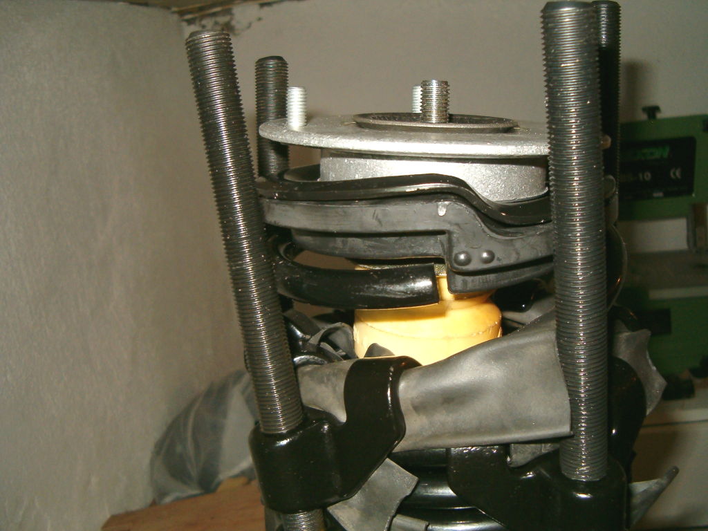 All edges flush against each other and the strut mount must rest on the support (there shall be a small gap between the spring and the strut mount). 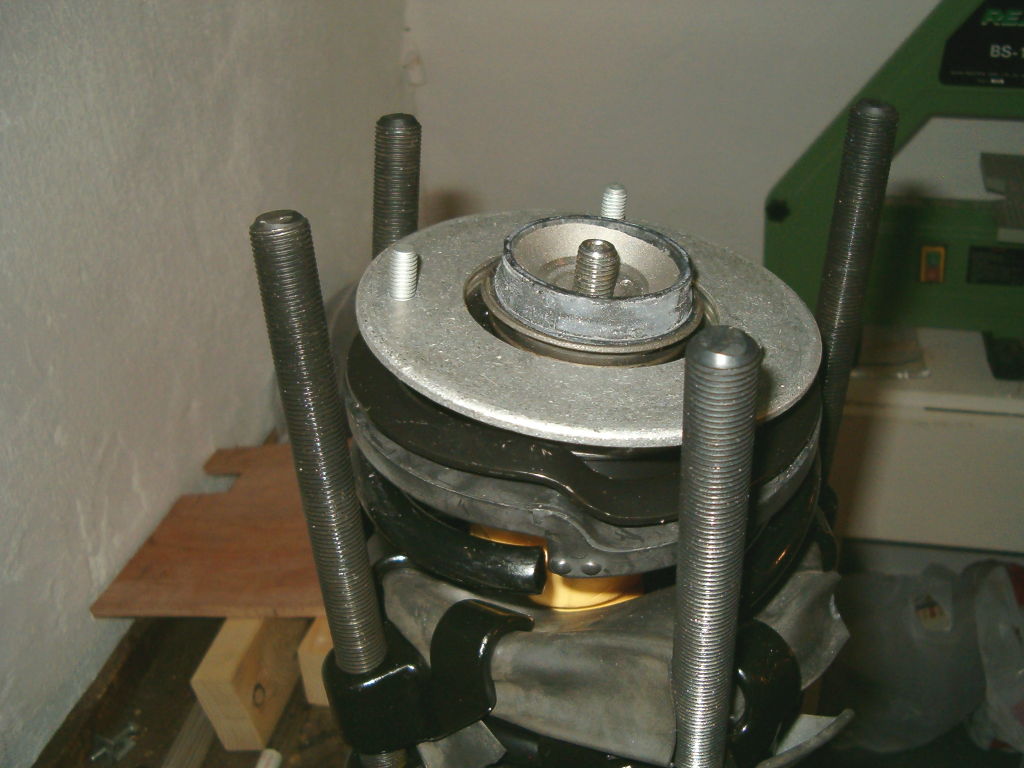 The stopper added. The assembly of the spring strut is exactly the reversal of the disassembly. It is recommedned though to have a helping hand - one holding the spring strut and the other tightening the selg-locking collar nuts.  Shiny and new parts installed! 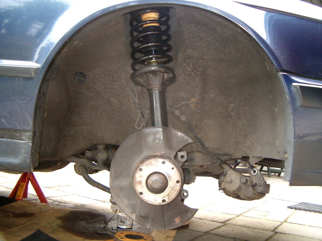 Shiny and new parts installed! Tightening Torques
|