| |
||
Removing DriveshaftThe driveshaft have just three mounting points. It is connected to the output flange of the gearbox, connected to the input flange of the final drive and in the middle it is supported by a center bearing. Step 1 : Towards The Gearbox Start by unmounting the driveshaft at the output flange of the gearbox. In between the gearbox and driveshaft there is a rubber flex disc (guibo) with the purpose to absorb torsional vibrations from the engine/transmission and to reduce shock load to the driveshaft and rear axle. My first intention was to unmount the rubber flex disc from the gearbox and remove the driveshaft and rubber flex disc in one piece. But it turned out that could not reach the nuts in an appropriate way to do so. So I decided to leave the rubber flex disc on the gearbox and only remove the driveshaft. 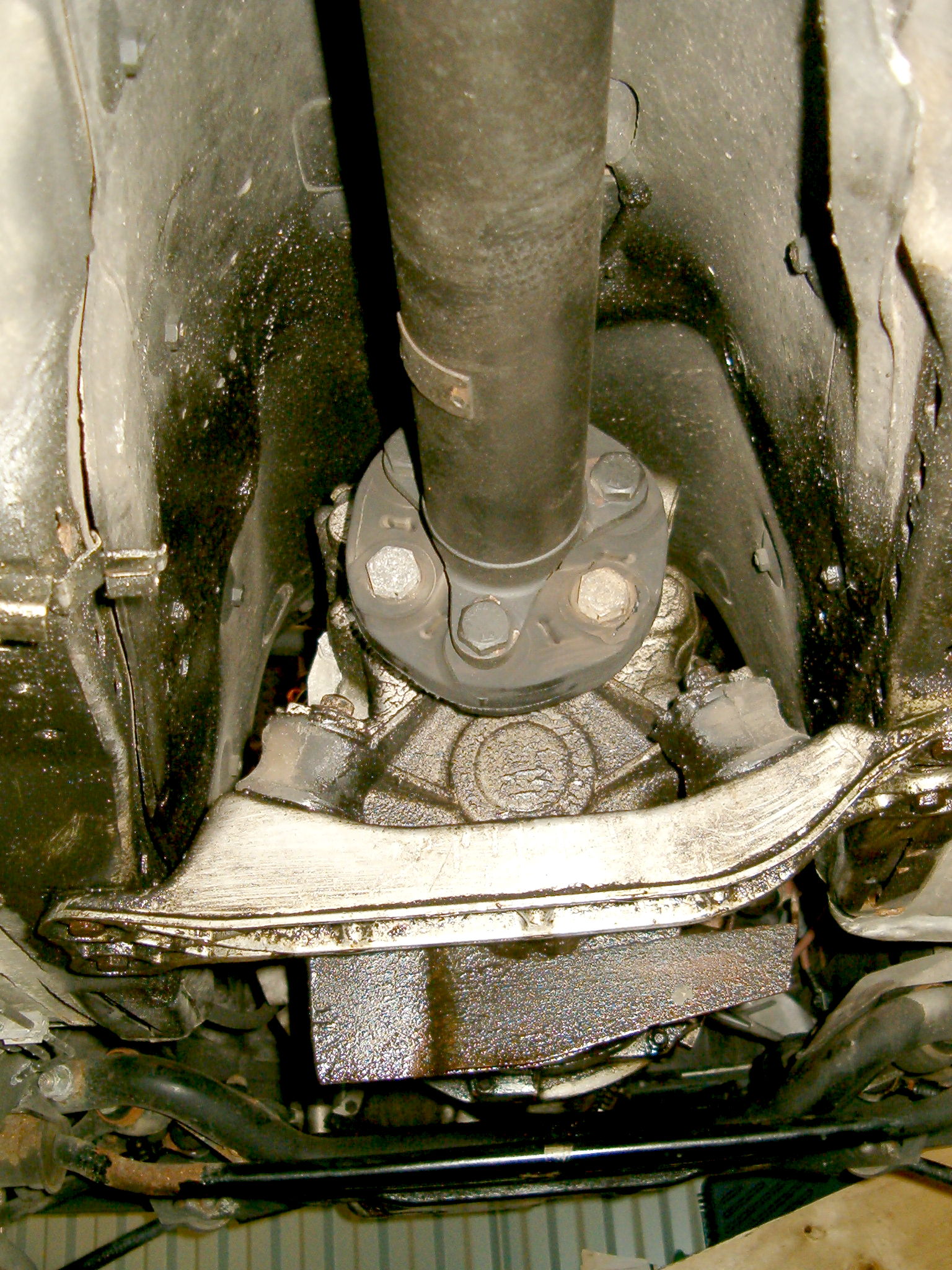 Driveshaft and rubber flex disc connected to the gearbox. The arrows points out the screws (and nuts on the other side) to be removed if you choose to leave the rubber flex disc on the gearbox. The basic idea is to insert a box-end or open-end wrench through one of the three holes in the transmission cross member and use it as a counterhold when you loosen the screws. 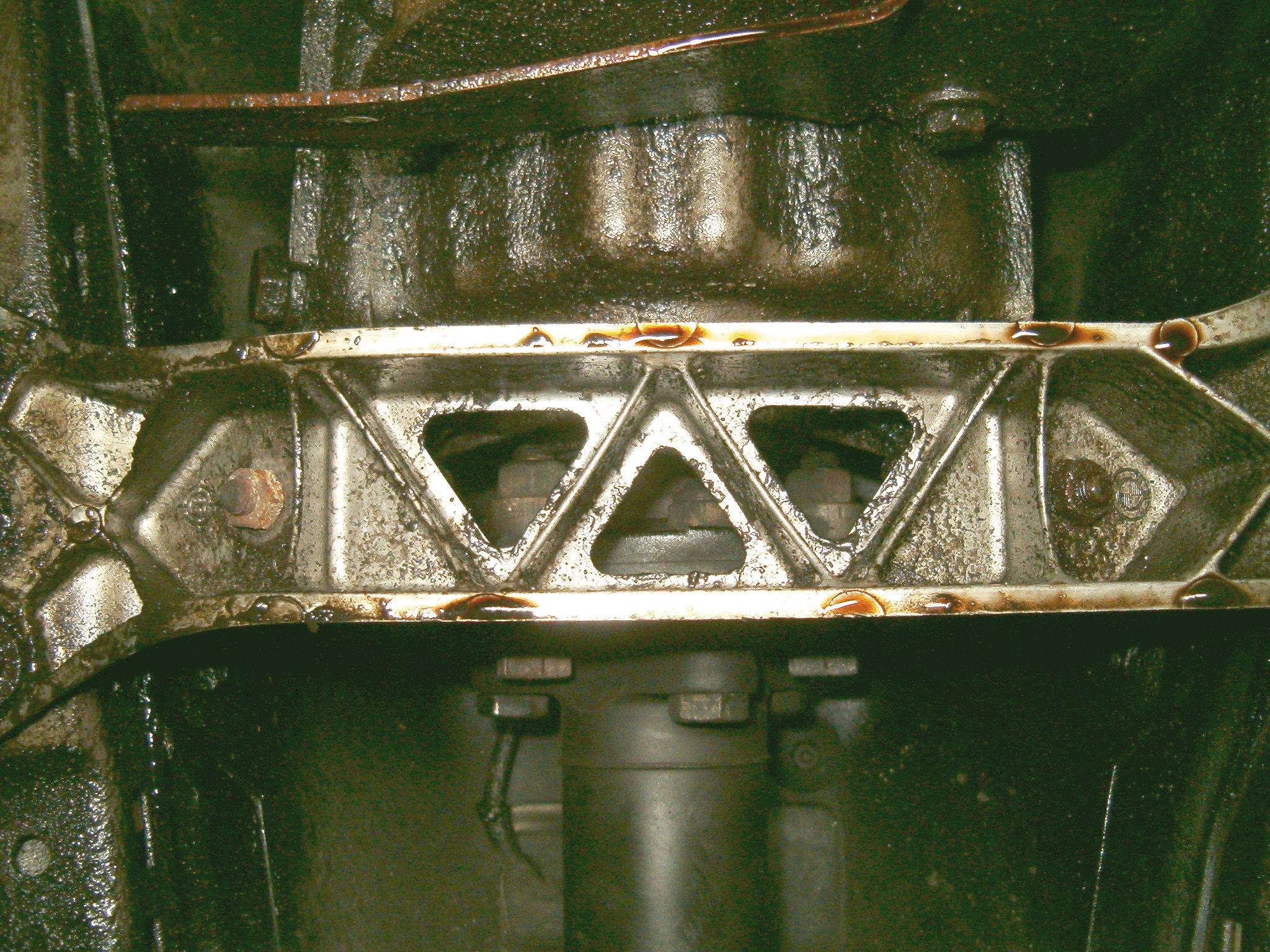 The three holes on the transmission cross member. When you have placed your counterhold wrench (tips is to let the wrench have the cross member as it's own counterhold so you can concentrate on the screw) then use a long breaker bar and a socket (a 1/2" 6-point socket and a 1/2" 500 mm long braker bar is recommended) to undo the screw. Remove completely all three pair of screws and nuts before proceeding to the other end of the driveshaft. Note that all nuts and screws are 19 mm hex heads. 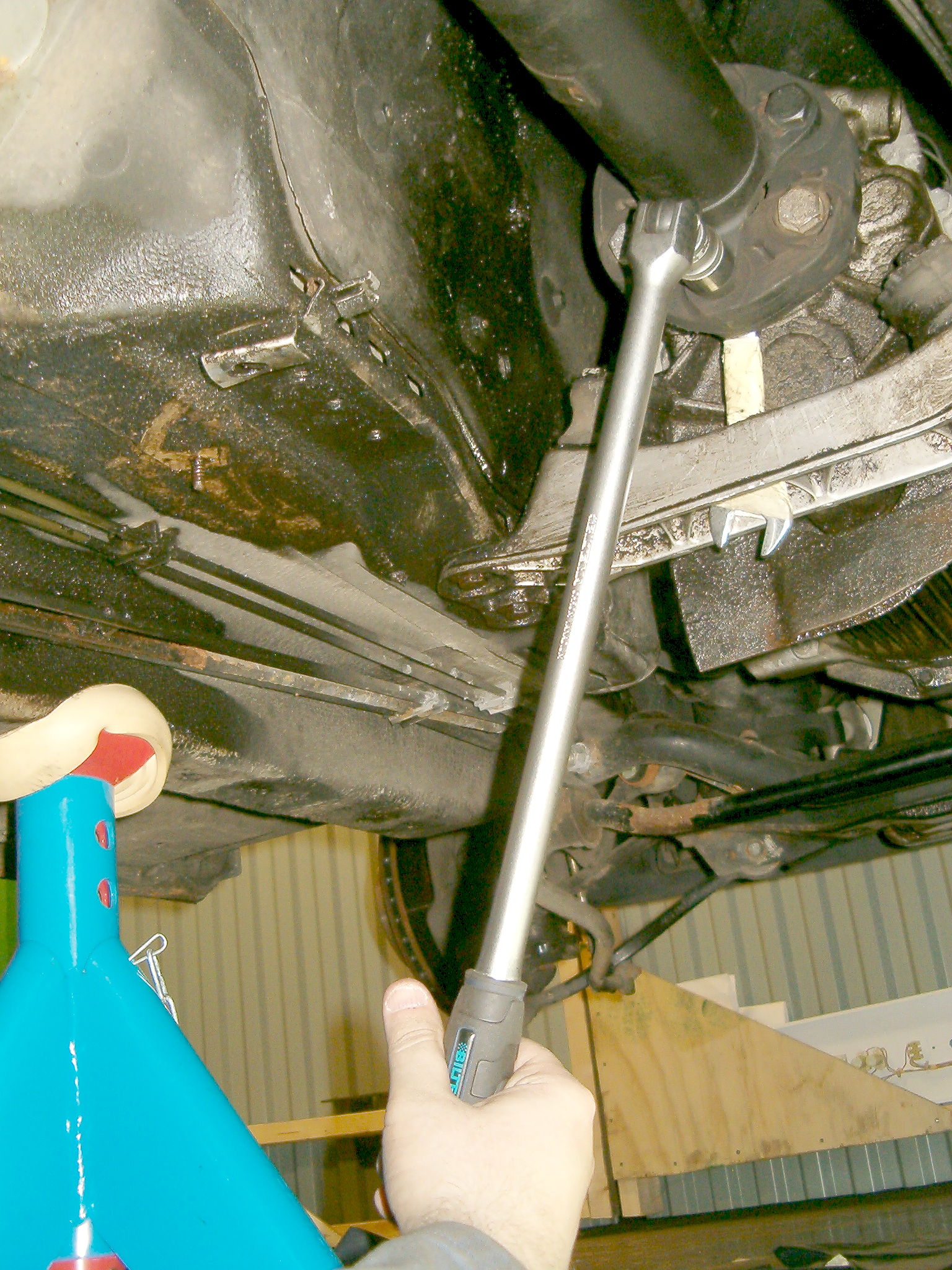 Use a box-end or open-end wrench on the nut as a counterhold and a long breaker bar to undo the screw. Since it is limited space you have to rotate the driveshaft until you get a good grip of a nut. To rotate the driveshaft simply put the gearbox into neutral, raise one of the rear wheels from the ground and turn it. This only works on cars with open differential, if your car is equipped with limited slip differential (or AGA differential!) you have to get both rear wheels of the ground. |
Step 3 : Towards The Final Drive
Next step is to remove the driveshaft from the final drive (rear differential). The connection between the driveshaft and the final drive consists of a CV joint (constant velocity). The driveshaft with the CV joint at the end is connected to the final drive input flange with six pin screws and 17 mm sex head self-locking nuts. The nuts are are accessible from an opening in the rear subframe. Use a long 17 mm box-end wrench to undo the nuts (there is no place for a socket). 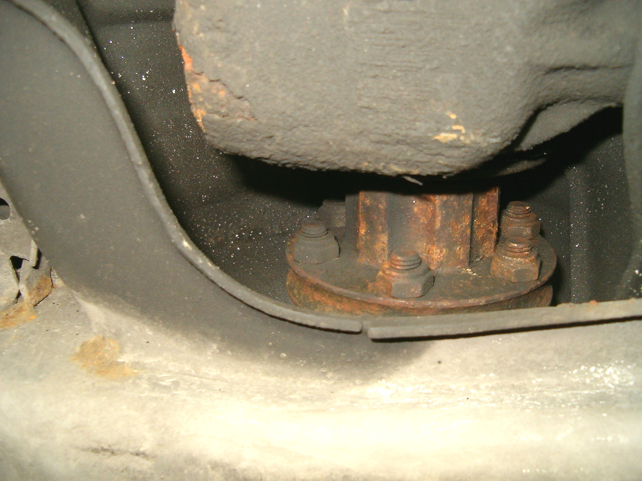 The six 17 mm sex head nuts accessible through the hole in the rear subframe. You can only access and undo two nuts at a time. To access the next pair of nuts you have to raise one rear wheel and rotate it until you can reach the next pair. Don't forget to put the gearbox into neutral and if you have a limited slip differential you have to raise both rear wheels from the ground. If you have an old car, like me, you might discover that you can not undo the nuts but instead you undo the pin screw and nut in one piece. This happened to me but it does not makeany big difference. It will work just as fine anyway. Step 4 : Towards Center Bearing And Removal The final mounting point is the center bearing support. This is mounted with two 13 mm hex head screws. Before removing you shall support the driveshaft with for example a floor jack or similar.  Center bearing support held by two 13 mm hex head screws. With the center bearing support removed you carefully push the driveshaft backwards (sliding the driveshaft together at the splined coupling) and pull it off at the front (against the gearbox). Now simply pull it off at the end (against the final drive). You might experience some resistance when trying to get it off from the final drive due to a sealing holding the two parts quite good together. Just use a tire bar or similar and give it a push on one of six screws you can access through the hole of the rear subframe. 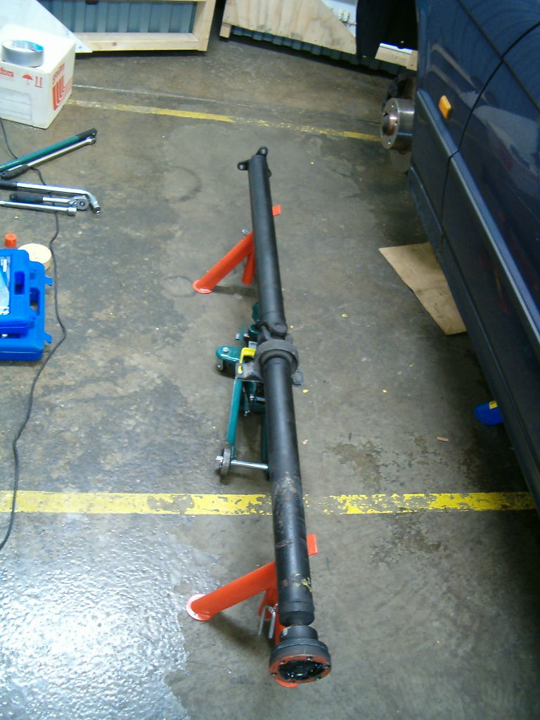 The removed driveshaft. If everything went well you should now have one nice and shiny driveshaft lying on your garage floor! Use care when removing and handling the driveshaft. Never let the yokes of the U-joint at the middle of the driveshaft to lock themselves (especially under load) otherwise you can damage the U-joiunt. In next part we start removing the gearbox! |